PAM Review: Energy Science & Technology, Vol. 7, 2020
ISSN 2205-5231 | Published by UTS ePRESS | https://epress.lib.uts.edu.au/student-journals/index.php/PAMR/index
Meta-analysis of concrete as a thermal energy storage medium
Guina Mourad1,* , Harry Lennox2, Madeline Turner3, Madison Traynor4
University of Technology Sydney, Faculty of Science, PO Box 123, Ultimo NSW 2007, Australia
1Guina.Mourad-1@student.uts.edu.au
2Harry.J.Lennox@student.uts.edu.au
3Madeline.Turner-1@student.uts.edu.au
4Madison.E.Traynor@student.uts.edu.au
* Author to whom correspondence should be addressed
DOI: https://doi.org/10.5130/pamr.v7i0.1596
Citation: Mourad, G., Lennox, H., Turner, M., Traynor, M. 2020. Meta-analysis of concrete as a thermal energy storage medium. PAM Review: Energy Science & Technology, 7, Article ID 1596. https://doi.org/10.5130/pamr.v7i0.1596
© 2020 by the author(s). This is an Open Access article distributed under the terms of the Creative Commons Attribution 4.0 International (CC BY 4.0) License (https://creativecommons.org/licenses/by/4.0/), allowing third parties to copy and redistribute the material in any medium or format and to remix, transform, and build upon the material for any purpose, even commercially, provided the original work is properly cited and states its license.
Abstract:
Solar energy is a renewable energy source however sunlight is only available during limited hours in the day. Researchers are looking towards an efficient energy storage system to ensure constant energy output. Concrete can be used as a filler material in a solar thermal energy storage system. This meta-study compared the heat capacity and thermal conductivity of concrete to other solid materials and concrete aggregates, allowing for the viability of concrete storage systems to be examined. The heat capacity of concrete was 5-10% higher than the comparative solid materials like brick and sand. Additionally, concrete without cement replacement materials were found to be more thermally conductive than concrete with added fly ash, blast furnace slag or silica fume with conductivity decreasing between 81-87%. However, concrete with the supplementary cementitious materials possess a higher heat capacity than concrete without cement replacement with capacity increasing by 25% at 30% replacement by fly ash with a grain size 300-600µm. When compared to the energy efficiency of other thermal energy systems, a concrete thermocline is shown to be less efficient than a molten salt two-tank energy storage system by less than 5%. Therefore, while concrete is a viable solid filler material in thermal energy storage systems, a molten salt two-tank thermal energy storage system is marginally more efficient. However, a partial cement replacement by supplementary cementitious materials can extend the effectiveness of the concrete thermal storage.
Keywords:
thermal energy storage, concentrated solar power, thermocline heat storage system, concrete, heat capacity, thermal conductivity, Supplementary cementitious materials
Abbreviations:
| SCM | Supplementary cementitious materials | SF | Silica fume |
| BFS | Blast furnace slag | LHS | Latent heat storage |
| TES | Thermal energy storage | SHS | Sensible heat storage |
| FA | Fly ash | PCM | Phase change materials |
1. Introduction
Fossil fuels are the main source of energy in today’s world, comprising 80% of the world’s total energy consumption (1). Due to the constant increase in the world’s energy consumption, the demand for the use of fossil fuels continues to increase, in turn having adverse effects on the environment from the burning of such resources, which has triggered the race to develop alternative means to energy production. Harnessing the Sun’s heat energy has been present in anthropologic history for centuries, solar power having been used as early as the 7th century BC, when humans started using materials to focus the Sun’s rays to start cooking fires.
This ever-increasing demand for energy consumption and recent projections predict that the primary energy consumption will rise by 48% in 2040 (2). As per the estimates provided by the US Energy Information Administration (EIA), fossil fuels are accountable for 86% of the total energy produced in the world. However, renewable energy has seen a growing proportion of energy consumption every year. In fact, the consumption of renewable energy is expected to increase by 6.2% annually, with an increase from 70,000 MW in 2020 to 140,000 MW by 2030 (3). In contrast, the proportion of fossil fuels used is decreasing; from 2002 to 2030, the consumption of oil is predicted to decrease by 1.8% annually (3).
The integration of Thermal Energy Storage (TES) ensures that all the stored solar energy is consistently available. Since the sun is only available to harness its energy 50% of the daylight hours it is vital to societal progression to find a means of utilizing this ‘stored’ energy at any time of the day. Rather than the solar energy at night part, solar thermal energy storage can provide a continuous supply of energy (4). Thermal energy storage, as shown in figure 1, is the storage of solar energy reflected from the sun in the form of heat. Energy is stored by heating, cooling, vaporizing, and melting (5). Energy is then extracted later by the reverse reaction (5). There are three different types of energy storage: sensible heat storage (SHS), phase change storage, and thermochemical storage (5). Thermal energy storage systems are needed because not only do they reduce the discrepancy between the demand and supply by conserving energy, but they also improve the performance and thermal reliability of the system (6). Therefore, designing efficient and economical TES systems is of high importance. The storage capacity, efficiency, storage duration, and costs are to be considered in designing a thermal energy storage system (6).
In this paper, A meta-analysis on the efficiency of single-tank thermocline and two-tank thermal energy storage systems. We assess the efficiency, thermal conductivity, and heat capacity of concrete and its performance over a long period of time as well as the possible cement replacement that would improve the thermal properties of concrete for the use as thermal energy storage medium.
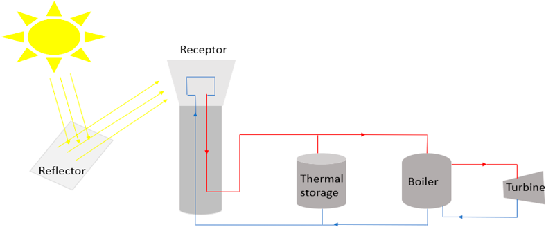
Figure 1 A diagram showing a thermal energy storage. The solar energy is reflected to the receptors by mirrors. The receptors being on top receives the light. As a heat exchanger, the receptors transfer the heat into a thermal energy. Which is then carried by the hot fluid, shown in red. The hot fluid travels from the receptor through the TES and boiler to the turbine, and the blue lines indicate the cold fluid travelling from the turbine to the receptor (7).
1.1 Classification and characteristics of EES:
1.1.1 Sensible heat storage:
Sensible heat storage is used as the most direct form of heat storage. This storage method is based on either increasing or decreasing the temperature of a solid or liquid medium, storing heat in the material during the charging and discharging process (5). The heat is then extracted from the storage system, releasing it with a decrease in temperature, as it is required to satisfy a load or level of demand such as space heating and domestic hot water (5). Sensible heat storage is based on the increase in enthalpy of the storage medium used (8). For the purpose of this meta study we will be investigating concrete as the storage material.
For sensible heat storage, the amount of heat that can be stored in a material is:
Equation 1: sensible energy storage; where Q is the amount of heat energy, m is the mass of the material, Cp is the specific heat capacity at constant pressure and dT is the change in temperature
1.1.2 Latent heat storage (LHS):
This type of storage system is based on the use of phase change materials (PCM) to store heat, with solid-liquid being the most common phase change, although others such as solid-solid and liquid-gas phase changes also exist (9). As the temperature increases, it receives energy, proportionally to the temperature increase, in the form of heat (9). When the temperature reaches melting point, the energy becomes latent heat as the PCMs change from solid to liquid. The same process also occurs in the liquid-gas phase change. This stored energy can be extracted by reversing this heating process (9).
The amount of heat that can be stored is (10):
where Q is the amount of heat energy, m is the mass of the material, Csp is the specific heat capacity as a solid, dT is the change in temperature, Lf is the specific latent heat of fusion, and Clp is the specific heat capacity as a liquid
1.1.3 Thermochemical heat storage:
In a thermochemical heat storage, a chemical reaction takes place, preferably one with high energy, and the products and heat are stored separately (11). When the reverse reaction takes place, the heat can be retrieved (11). Of the other two types, thermochemical heat storage can store at the highest density of energy (11).
1.2 Classification and characteristics of TES:
1.2.1 One-tank thermocline TES:
This is a direct thermal energy storage system. A thermocline, as shown in Figure 2, is a layer in a body of fluid that is marked by a rapid temperature change over a relatively short depth.
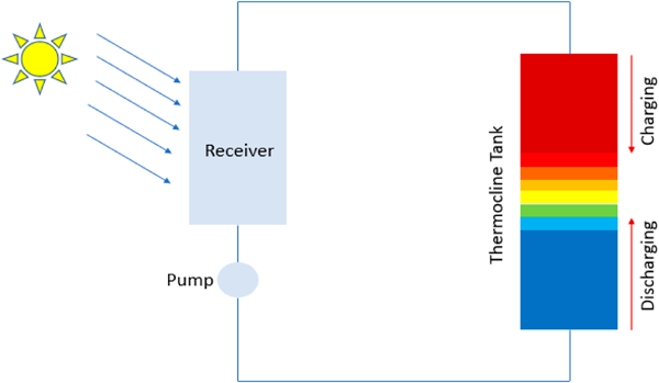
Figure 2 Schematic of a single-tank thermocline energy storage system, showing clearly the change in temperature T from cold to hot (blue to red) which creates a thermal gradient inside the tank. During the charging phase, heat flows from the hot portion to the cold portion of the tank. In discharging phase, the heat flows from cold to (13).
In a storage tank, a high-temperature fluid flows down to the bottom into a low-temperature fluid. This change in temperature generates thermal energy, which then can be stored in the medium for future use. The system is equipped with a thermal gradient separating the two temperature regions. In charging phase, the thermal gradient of the thermocline material goes downwards and upwards in discharging phase (12).
1.2.2 Two-tank TES:
In the two-tank TES system, represented below in Figure 3, the fluid is stored in two separate tanks hot and cold. The fluid flows from the high temperature tank through the steam generator to the cold storage tank.
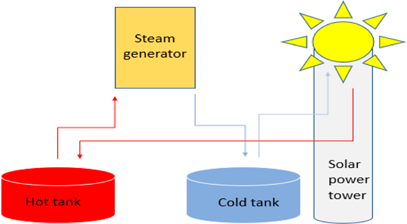
Figure 3 Two-tank energy storage system. The red and blue lines indicate hot and cold fluid, respectively. The solar power tower uses the heat and channels it into the hot fluid. Cold fluid comes out of the steam generator and turbine (14).
1.2.3 Packed bed:
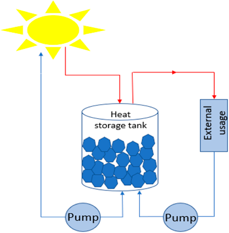
Figure 4 Schematic of a packed bed thermal energy storage system. The red and blue lines represent hot and cold fluids. The hot fluid enters the top of the tank and the cold fluid enters the bottom of the tank, causing the thermocline within the tank.
1.3 Types of concrete
There are many types of concrete which are used in a wide range of applications, from homes, streets and pavement blocks, to dams and bridges. Concrete is used also as a storage medium in the thermocline system. Some types of concrete that are used include reinforced concrete and prestressed concrete.
Reinforced concrete is a type of concrete that contains reinforcing bars, usually made of steel, to increase its strength. The rebar is first arranged into its final position, and then concrete is poured on top of the rebar (15). When it undergoes temperature changes, the steel will expand and contract with the concrete instead of cracking it (15). Its advantages include high fire and water resistance, requiring low maintenance, being able to be moulded into a wide variety of shapes, and under the right conditions, reinforced concrete will not experience any reduction in its load-carrying abilities (15). However, disadvantages include having a very low tensile strength, and its low strength for its volume means that large concrete pieces will be made (15).
Prestressed concrete combines the compressive properties of concrete with the tensile strength of steel (16). For this type of concrete, steel bars are introduced into the concrete, and then it has stress, or compression, introduced to it while it is being created, hence “prestressed”, and that way, the concrete can counteract the stresses that will be delivered to it during usage(16). This type of concrete is ideal for the construction of infrastructure that requires large beam spans, such as in bridges to increase its span (16).
1.4 Composition of Concrete:
1.4.1 Basic components of concrete
Concrete is composed of aggregates, Portland cement and water (17). The aggregates are Coarse aggregate mainly gravel or stone, and fine aggregate including sand. The proportions of this components may vary and is directly related to the mechanical, physical, and thermal properties of the concrete (17). Portland cement is a common type of cement. It is a basic ingredient in the concrete composition.
1.4.2 Cement Replacement Materials
The production of Portland cement causes CO2 emission which is released into the environment (17). The equation is as follows:
The production of cement requires energy (+heat, in the equation). To reduce the costs of concrete production and limit its environmental impact, cement is replaced by other materials that have comparable properties as cement (17). These materials are called supplementary cementitious materials (SCM) (18). A specified percentage of SCM is added to the concrete mixture to partially replace some of the Portland cement (18).
The common cement replacement materials are fly ash (FA), silica fume (SF) and blast furnace slag (BFS). Fly ash is a fine powder produced by coal burning; it produces a compound like Portland cement when mixed with water and lime (19). Silica fume is a very fine particles; it is one of the products of producing silicon or silicon alloys (19). Blast furnace slag is a product of producing iron; it is made by combining the granulated slag with Portland cement (19).
2. Methodology:
The aim of this meta study is to assess the viability of concrete with different compositions as a filler material in the thermal energy storage. The information for the meta-study were extracted from the scientific databases SCOPUS, ScienceDirect, Google Scholar and Research Gate. Keywords such as concrete thermocline, concrete, thermal conductivity, thermal energy storage, solar energy storage, and thermal capacity were used to locate relevant papers which were further filtered by papers written in the past 10 years to ensure the data pertains to current technologies and data. The data included in the analysis is extracted from papers that were supported by experimental data to ensure that these sources are reliable.
In order to analyse the viability of a concrete as a storage medium in TES, the energy output, heat capacity and thermal conductivity were taken as standards to compare concrete TES to alternative materials and thermal systems. For example, the energy output of thermocline system was compared to a two-tank system based on the energy output per year of the two systems over a varied solar multiple, defined as the ratio of solar energy collected from concentrated solar plants to the amount of discharged energy required. Following this the viability of concrete was determined by using the heat capacity of concrete as a standard of comparison to other solid materials, then the type of concrete was narrowed down by examining the optimal proportion of SCM in concrete by contrasting the thermal conductivity values of the concrete samples.
3. Results and Discussion:
The determination of the efficiency of a thermocline system in practical circumstances relies upon the energy output of the thermocline system over a large period, showing the deterioration of the thermocline system and anticipated lifespan of the system. The optimum concrete TES is reliant upon TES structural efficiency as well as the thermal properties of the concrete and concrete aggregates.
3.1. Thermocline efficiency
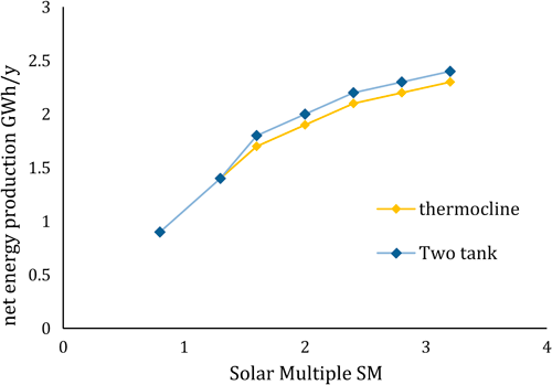
Figure 5 Net energy production (GWh/y) molten-salt two-tank system and thermocline for the same solar multiple input. The thermocline energy storage system is marginally less efficient than the two-tank thermal energy storage system (12).
The thermocline system is shown to be less energy efficient than the two-tank thermal energy storage system by 1GWh/y for solar multiples exceeding 1.5. When the energy input is equal to the required energy in a 1:1 ratio the difference between the output energies of TES and two tank systems is negligible. At solar multiple 1.5 the input energy markedly exceeds the energy required and differences in the output energy of the systems becomes noticeable. The two-tank thermal system relies upon molten salts to store heat energy. Between the two tanks exists a temperature gradient and due to the large heat capacity of the molten salts, the temperature difference existing between the tanks can be larger resulting in a higher amount of discharged energy. Since the TES uses solid materials the heat capacity of such materials is lower than that of molten salt at any given temperature, decreasing the amount of thermal energy stored in the system. The decrease in heat creates a smaller temperature gradient resulting in lower energy outputs from the system.
3.2 Solid material heat storage capacity
Specific heat capacity (J/kg.K) is defined as the input of thermal energy needed to increase the temperature by a specific factor for a specified mass (22). In other words, it is a factor to measure the effectiveness of a material in absorbing heat. The solid storage medium has the capacity to store large amounts of heat. Concrete has a heat capacity 880 J/kg.K Figure 6) with variations dependent on the composition of the concrete. Of the solid materials concrete is shown to have a heat capacity higher than brick, cast iron, granite, and sand.
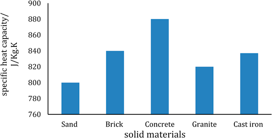
Figure 6 Specific heat capacity of concrete. Of the five graphed here, concrete has a heat capacity of 880 J/kg.K, and brick has a heat capacity value of 880 J/kg.K (20 & 21).
With a heat capacity value 4.7% larger than that of brick (heat capacity of 840J/kg.K) this indicates larger amounts of energy is needed in the material to raise the temperature of the material. As a result, more energy is stored over a thermocline region. As a part of the thermocline system, concrete has the highest operating temperature between 650-700K creating a gradient enabling electrical discharge.
3.3 Concrete thermal properties:
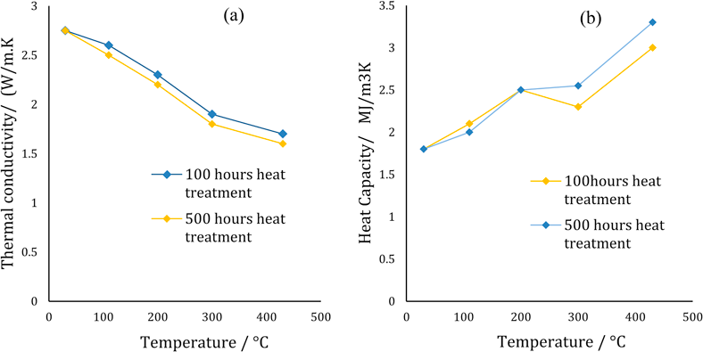
Figure 7 (a) Thermal conductivity of concrete decreases when exposed to temperature in the range of (0°C to 500°C). The rate at which 500 hours preheated concrete decreased is higher than that preheated for 100 hours. The total average decrease in the thermal conductivity is of 1W/m.K at 500°C. (b) The heat capacity of concrete increased when exposed to temperatures in the range of (200°C to 500°C). the rate at which the heat capacity of the 500 hours preheated sample increased is higher than that of 100 hours preheated sample (23).
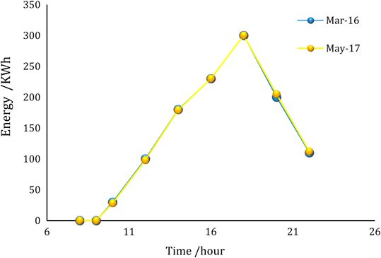
Figure 8 The energy output of the concrete thermocline system is shown to be unchanged from the March of 2016 to May 2017; long term performance (23).
As the concrete is exposed to heat the primary cause of a decrease in energy output would be changes to the concrete structure. This results in changed thermal properties due to exposure to high temperatures and cyclic thermal loading. Over a 500-hour period concrete samples that were heat treated showed a higher heat capacity than the 100-hour heat treated sample indicating a slight change in the structure of the concrete samples as more energy was needed to raise the temperature of the mass of concrete (Figure 7b). In conjunction with the decrease of thermal conductivity by 1W/m.K by the 500-hour heat treated sample (Figure 7a), the results shows that the application of heat to the concrete samples increases the amount of energy stored in the concrete over a larger thermal gradient as thermal conductivity is reduced. Hence it can be surmised that extended heat treatment would cause some decrease in thermocline efficiency.
Contrarily, after 15 months of use the thermocline storage system shows negligible change in energy output (Figure 8). The energy output at 20 hours shows an increase of 7kWh in May 2017 compared to March 2016. The 3.5% increase in output could potentially be due to the change in thermal properties (Figures 7a and b) that would increase the thermal storage of the system. This suggests that the application of heat to concrete does not reduce the capability of concrete performance in a thermocline system.
3.4. Thermal conductivity of concrete composed of varying amounts of supplementary cementitious materials
The composition of the concrete impacts upon the thermal conductivity of the concrete as the addition of aggregates and substances changes the internal structure of the concrete and therefore the thermal properties of the concrete. The highest value of thermal conductivity of concrete is obtained for specimens produced with 100% Portland cement while lower thermal conductivity value occurred at 30% BFS replacement (Figure 9a). From the thermal conductivity value of 1.23 W/m.K the SF showed the greatest decrease in thermal conductivity showing a decrease by 16% compared to a decrease of 14% for FA and 12% for BFS at a proportion of 15% cement replacement. The decrease in thermal conductivity for SF also decreases at a higher rate between 7.5% and 15%. The FA has a higher rate of decrease as the BFS rate of decrease is lower between 15% and 30%. A 16% decrease in thermal conductivity was also seen in the SF (Figure 10) and shows a further decrease by 31% at 25% SF component. This supports the notion that SF addition results in the largest decrease in thermal conductivity between the three additives. For a more accurate depiction of the effect of cement replacement proportion on thermal conductivity a measurement would need to be taken for every value between 0-30% for SF, FA and BFS. Similarly, a mixture of BFS, SF and FA shows a decrease in the thermal conductivity of concrete (Figure 9b).
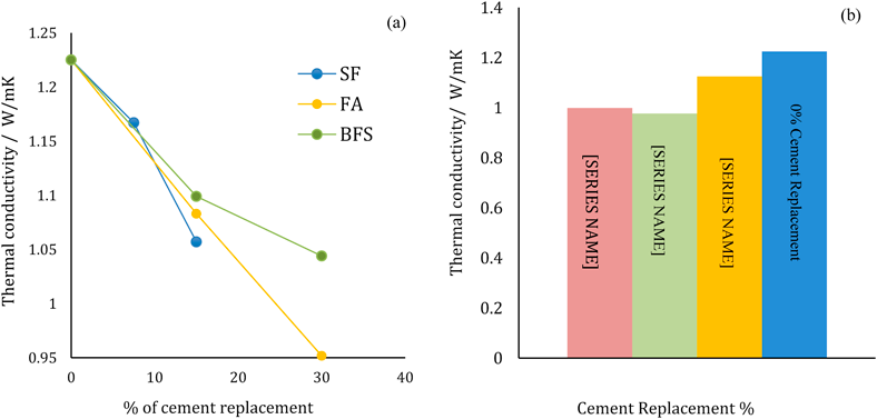
Figure 9 (a) Thermal conductivity decreases upon the replacement of cement with FA, SF, and BFS with a percentage of 0%, 7.5%, and 15%. Blast furnace slag decreased the thermal conductivity slower than silica fume and fly ash. Replacing cement with 30% fly ash decreased the thermal conductivity by more than 20% (24). (b) Percentage replacement of cement by mixed proportions of multiple materials decreased the thermal conductivity (W/mK). It is shown the 0% cement replacement concrete had the most thermal conductivity (24).
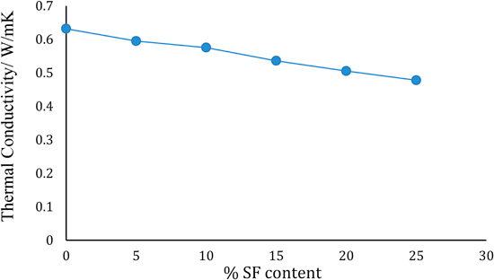
Figure 10 The Thermal Conductivity (W/mK) decreases upon the percentage replacement of Portland cement by silica fume in the range of 0% to 30% (25).
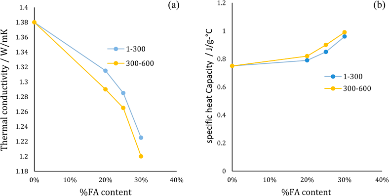
Figure 11 (a)The percentage of Portland cement replacement by fly ash with a range of 0% to 30% decreased the thermal conductivity of the concrete mixture approximately to 1.2 W/m.K. the rate at which the larger grain size (300-600) is higher than that of smaller grain size (1-300µm). (b)The specific heat capacity increased to a value of 1 J/g.°C for a 30% FA content. The rate at which the specific heat capacity for the larger grain (300-600µm) is higher than that for (1-300µm) grains (26).
A similar result was observed in another experiment (26), where the partial replacement of cement by FA resulted in a decrease in the thermal conductivity. The experiment investigated the percentage addition of FA content with grain size 1-300 by 20%, 25%, and 30% FA content; the results showed that the thermal conductivity of concrete decreased by 0.065 W/m.K, 0.095 W/m.K, and 0.155 W/m.K respectively. For a grain 300-600µm in size the thermal conductivity decreased by 0.09 W/m.K, 0.115 W/m.K, and 0.18 W/m.K respectively. The thermal conductivity (figure 11a) was compared between different %FA content, taking into consideration this time the grain size. The graph shows that the thermal conductivity decreased upon the addition of fly ash to reach a value of 1.225 W/m.K for 1-300µm grains, higher than that achieved by larger grains, 300-600µm at 30% FA which was 1.2 W/m.K. The rate at which the thermal conductivity decreased is higher for large grain size 300-600µm than small FA grain size 1-300µm.
The heat capacity (figure 11b) increased upon the percentage replacement of cement by FA content. The heat capacity was equal to 0.75 J/g°C at 0% replacement. For 20%, 25%, and 30% FA of grain size 1-300µm, the heat capacity increased to 0.79 J/g°C, 0.85 J/g°C, and 0.96 J/g°C respectively. A higher heat capacity was observed for a grain size 300-600µm, the recorded values were 0.82 J/g°C, 0.9J/g°C, and 0.99J/g°C for 20%, 25%, and 30% FA content. The rate at which the heat capacity increased is higher for 300-600µm grain size than 1-300µm grain FA size. The highest value of heat capacity 0.99J/g°C corresponds for a 30% FA content with a grain size 300-600µm.
4. Conclusions
Thermal energy storage is the storage of energy in the form of heat by heating or cooling a filler material. The stored energy is then saved for later use. This meta-study aimed to assess the efficiency of different concrete compositions as a filler material in the thermal energy storage system by looking into its thermal conductivity and heat capacity. The one-tank concrete thermocline TES system was shown to be a less efficient energy storage system in comparison to the molten-salt two-tank storage system by less than 5%. This meta study reveals that the energy output of the molten-salt two-tank system is higher than the energy output of the single tank thermocline by 1GWh/y for solar multiple exceeding 1.5. Concrete among the indicated solid materials is the most appropriate material to use as a thermal storage medium due to the high heat capacity valued 880 J/kg.K. Our analysis of the recorded experimental behaviour of concrete in March 2016 and May 2017 has shown that concrete has a sustained performance over a long period of time. Of the concrete compositions, we found that the replacement of cement by supplementary cementitious materials tend to decrease the thermal conductivity of the mixture and increase the heat capacity. The heat capacity was recorded 1 (J/g.°C) for 30% FA content the highest capacity between all other mixtures.
Acknowledgments
The authors of this paper would like to acknowledge Dr Jurgen Shulte, Blake Regan, and Brendan Boyd-Weetman for their contributions to the editing process of this paper. Additional thanks are extended to Energy Science and Technology class peers for their feedback in the peer review process.
References and Notes
(1) Ioan Sarbu, Calin Sebarchievici. A Comprehensive Review of Thermal Energy Storage. Sustainability 2018 Jan 14;10(2):191. https://doi.org/10.3390/su10010191
(2) Moharir RV, Gautam P, Kumar S. Chapter 4 - Waste Treatment Processes/Technologies for Energy Recovery. Current Developments in Biotechnology and Bioengineering 2019:53-77. https://doi.org/10.1016/b978-0-444-64083-3.00004-x
(3) Solangi KH, Islam MR, Saidur R, Rahim NA, Fayaz H. A review on global solar energy policy. Renewable and Sustainable Energy Reviews 2011;15(4):2149-2163. https://doi.org/10.1016/j.rser.2011.01.007
(4) Energy and Exergy Analyses of Thermal Energy Storage Systems. Thermal Energy Storage Chichester, UK: John Wiley & Sons, Ltd; 2010. p. 233-334. https://doi.org/10.1002/9780470970751.ch6
(5) Thermal Energy Storage (TES) Methods. Thermal Energy Storage Chichester, UK: John Wiley & Sons, Ltd; 2010. p. 83-190. https://doi.org/10.1002/9780470970751.ch3
(6) Sørensen B. 5 - Energy transmission and storage. Renewable Energy (Fifth Edition) 2017:569-646. https://doi.org/10.1016/b978-0-12-804567-1.00005-0
(7) Pelay U, Luo L, Fan Y, Stitou D, Rood M. Thermal energy storage systems for concentrated solar power plants. Renewable and Sustainable Energy Reviews. 2017;79:82-100. https://doi.org/10.1016/j.rser.2017.03.139
(8) Kalaiselvam S, Parameshwaran R. Thermal energy storage technologies for sustainability. Amsterdam: Elsevier; 2014.) https://doi.org/10.1016/b978-0-12-417291-3.00003-7
(9) Cárdenas B, León N. High temperature latent heat thermal energy storage: Phase change materials, design considerations and performance enhancement techniques. 2013. https://doi.org/10.1016/j.rser.2013.07.028
(10) Nomura T, Okinaka N, Akiyama T. Technology of Latent Heat Storage for High Temperature Application: A Review. ISIJ International. 2010;50(9):1229-1239. https://doi.org/10.2355/isijinternational.50.1229
(11) John E, Hale M, Selvam P. Concrete as a thermal energy storage medium for thermocline solar energy storage systems. Solar Energy 2013;96:194-204. https://doi.org/10.1016/j.solener.2013.06.033
(12) Cocco D, Serra F. Performance comparison of two-tank direct and thermocline thermal energy storage systems for 1 MWe class concentrating solar power plants. Energy 2015;81:526-536. https://doi.org/10.1016/j.energy.2014.12.067
(13) Manu K, Deshmukh P, Basu S. Rayleigh–Taylor instability in a thermocline based thermal storage tank. International Journal of Thermal Sciences. 2016;100:333-345. https://doi.org/10.1016/j.ijthermalsci.2015.10.016
(14) Al-Chaaban F, Ghamrawi A, Haykal C. Comparative Study on Photovoltaic and Thermal Solar Energy Concentrators. ; 2013.
(15) McCormac CJ, Brown HR. Design of Reinforced Concrete. 9th ed. John Wiley & Sons; 2013.
(16) Dolan CW, Hamilton HR. Prestressed Concrete. 1st ed. Springer International Publishing; 2019. https://doi.org/10.1007/978-3-319-97882-6
(17) Dunuweera SP, Rajapakse RMG. Cement Types, Composition, Uses and Advantages of Nanocement, Environmental Impact on Cement Production, and Possible Solutions. Advances in Materials Science and Engineering 2018 Apr 4,;2018:1-11. https://doi.org/10.1155/2018/4158682
(18) Claisse PA. Cements and cement replacement materials. 2016. p. 163–76. https://doi.org/10.1016/b978-0-08-100275-9.00018-8
(19) A. Brief Review. Period #10 Notes: Admixtures & Cement replacement materials.
(20) Sarbu I, Sebarchievici C. A Comprehensive Review of Thermal
(21) Usher B. Renewable energy. New York: Columbia University Press; 2019.
(22) Feidt M. Finite Dimensions Thermodynamics beyond Thermomechanical Systems. 2018:1-35. https://doi.org/10.1016/b978-1-78548-233-5.50001-8
(23) Hoivik N, Greiner C, Barragan J, Iniesta AC, Skeie G, Bergan P, et al. Long-term performance results of concrete-based modular thermal energy storage system. Journal of Energy Storage 2019;24:100735. https://doi.org/10.1016/j.est.2019.04.009
(24) Demirboğa R. Thermal conductivity and compressive strength of concrete incorporation with mineral admixtures. Building and Environment 2007;42(7):2467-2471. https://doi.org/10.1016/j.buildenv.2006.06.010
(25) S. A. Farhan, M. F. Khamidi, M. H. Murni, M. F. Nuruddin, A. Idrus, A. M. Al Yacouby. Effect Of Silica Fume And MIRHA On Thermal Conductivity Of Cement Paste. WIT Transactions on the Built Environment 2012 Jan 1,;124:331. https://doi.org/10.2495/hpsm120291
(26) Vinayakrishna D Kunthe, Dr. G Manavendra, Mr. Vaibhav M Sondur. Effect of thermal properties on fly ash-based concrete. 2018.


