PAM Review: Energy Science & Technology, Vol. 7, 2020
ISSN 2205-5231 | Published by UTS ePRESS | https://epress.lib.uts.edu.au/student-journals/index.php/PAMR/index
Meta study on the optimisation of thermoacoustic cooling systems for efficiency and cooling load
Daniel Holland1,*, Nicholas Berryman2,*
University of Technology Sydney, Faculty of Science, PO Box 123, Ultimo NSW 2007, Australia
1Daniel.R.Holland@student.uts.edu.au
2Nicholas.Berryman@student.uts.edu.au
* Authors to whom correspondence should be addressed.
DOI: https://doi.org/10.5130/pamr.v7i0.1593
Citation: Holland, D., Berryman, N. 2020. Meta study on the optimisation of thermoacoustic cooling systems for efficiency and cooling load. PAM Review: Energy Science & Technology, 7, Article ID 1793. https://doi.org/10.5130/pamr.v7i0.1593
© 2020 by the author(s). This is an Open Access article distributed under the terms of the Creative Commons Attribution 4.0 International (CC BY 4.0) License (https://creativecommons.org/licenses/by/4.0/), allowing third parties to copy and redistribute the material in any medium or format and to remix, transform, and build upon the material for any purpose, even commercially, provided the original work is properly cited and states its license.
Abstract:
The emerging field of thermoacoustic cooling systems (TACS) has been explored in recent years, combining the disciplines of acoustics and thermodynamics to provide an alternative to mainstream cooling technologies. This hybridised system allows a system of travelling or standing waves to absorb and release thermal energy at different points spatially, which is then harnessed to produce a cooling effect. This meta-analysis will focus on analysing parameters such as stack plate spacing and selection of a working fluid, in order to optimise the system. As this will directly impact the temperature gradient, as the temperature gradient is the core operator in the cooling process. The above parameters were examined with a combination of comparative and normalisation techniques, to synthesise data from varied experimental sources and produce accurate conclusions. The parameters investigated had differing effects on the system with regards to COPR and maximum cooling power, due to cooling power and input acoustic power increasing at different rates. The meta study concluded that a ratio of parallel-plate stack spacing to thermal penetration depth of was ideal for maximising cooling load, where as a ratio of approximately was ideal for achieving maximum COPR.
Keywords:
cooling load, coefficient of performance, COPR, thermoacoustic effect; thermoacoustic cooling; thermoacoustic refrigerator; stack spacing; working fluid
1. Introduction
Growing concern for environmental issues in recent years has led to a re-evaluation of current refrigeration technologies, prompting an interest in ecologically sustainable alternatives. In older cooling systems, it was common to use environmentally harmful refrigerants such as chlorofluorocarbons (freon variants) [1-3]. The results of using such refrigerants has been linked to ozone degradation [3,4] and amplification of the greenhouse effect [5]. The current literature reflects these concerns and alternative technologies for refrigeration are being investigated. These include but are not limited to; thermoelectric refrigerators, ammonia refrigerants and pulse tube refrigerators, to rectify the issue [6,7]. However, a promising alternative technology is thermoacoustic cooling, as it yields a robust design with sustainable components, enabling use in long term applications [1,8].
Thermoacoustic cooling is a process of converting the work done by acoustic waves into a heat transfer system (i.e. a refrigerator) using high amplitude travelling or standing waves, such as those produced via an acoustic generator [6,9]. The design of a standard thermoacoustic cooling system (TACS), comprises a multi-component system which can be made without moving parts [5,7,8,10]. This means that the common components of TACS designs; the stack (in standing-wave units) or regenerator (travelling-wave), resonator tube and heat exchanges; are stationary components requiring little maintenance.
This study aims to analyse parameters that directly affect the coefficient of performance and cooling load for the optimisation of thermoacoustic technology. By optimising the temperature gradient, the efficiency and output of thermoacoustic cooling is optimised. This will be achieved by synthesising data found in the existing literature to analyse and collate factors that have yielded increases in cooling outputs and efficiency.
1.1 Thermodynamics of Thermoacoustic Cooling Systems (TACS)
There are two main categories of thermoacoustic devices – standing-wave and travelling-wave – based on the properties of the driving acoustic wave used. Designs in both categories typically use a long, closed tube known as a resonator, in which a working fluid (gas) oscillates with supplied acoustic power. Standing-wave devices utilise the interference of a wave on itself as it reflects 180° out of phase from the end of the resonator to create a standing pressure wave across the stack [6,8,11,12]. Similarly, travelling-wave devices use a wave reflected 90° out of phase, to create an acoustic travelling-wave system across the regenerator [8]. The stack and regenerator themselves consist of a block of either parallel stacked plates, a mesh-grid or honeycomb lattice along which the working fluid can flow through and interact with the material in multiple channels with a large effective surface area, enacting a thermodynamic cycle as shown in Figure 1 [8,12].
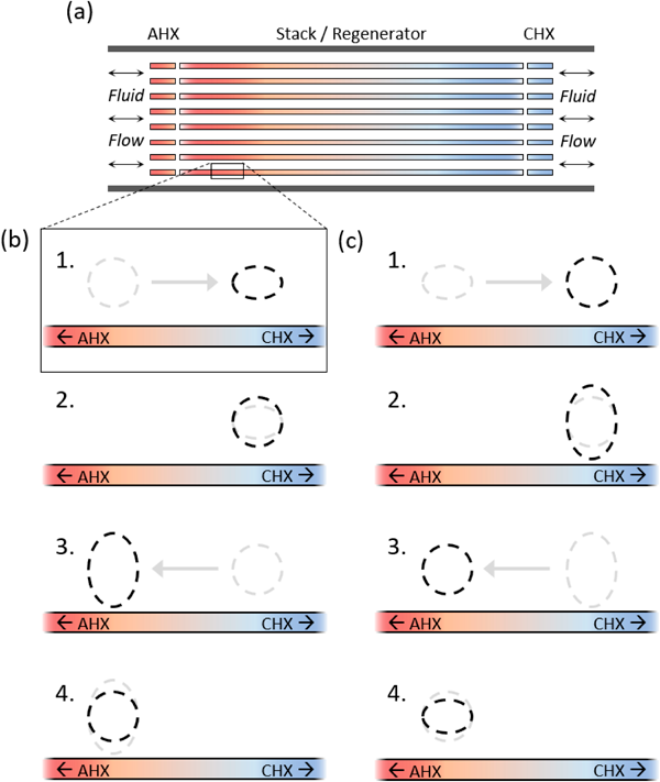
Figure 1 (a) Cross-sectional diagram of a part of the resonator tube, including the stack or regenerator, with the ambient and cold heat exchanges (AHX and CHX respectively) at each end. (b) Thermodynamic cycle of a standing-wave thermoacoustic refrigerator (SWR). 1 – Adiabatic compression as the packet is pushed toward a higher-pressure region; 2 – Isobaric heat absorption, pulling heat from the stack at one end; 3 – Adiabatic expansion as the packet is pushed back to lower pressure; 4 – Isobaric heat release back into the stack at the other end, generating a temperature gradient. (c) Thermodynamic cycle of a travelling-wave thermoacoustic refrigerator (TWR). 1 – Isobaric heat expansion, pulling heat from the regenerator surface as the packet is pushed across it; 2 – Isothermal expansion, pulling further heat from the regenerator at one end to expand as the pressure drops; 3 – Isobaric compression, letting heat out into the regenerator as the packet is pushed back across it; 4 – Isothermal compression as the pressure increases, causing heat to flow into the end of the regenerator and thereby form a temperature gradient.
To drive the system, an acoustic generator is attached to produce acoustic waves in the working fluid [6,7,11]. Many TACS designs simply use a speaker to generate the acoustic work input; others utilise thermoacoustic engines in a cascade effect, effectively utilising electrical power or even waste heat to generate a spontaneous acoustic resonance in the working fluid [9]. Some TACS designs make use of waste heat (such as that from other energy production sources) and solar energy for transformation, though this is still not ready for practical application as it requires high temperature (100°C - 300°C) [13].
In a thermoacoustic refrigerator, the processes depicted in Figure 1 occur on a small scale, repeated spatially along the channels of the stack or regenerator to transport heat from one end to the other and gradually form a temperature gradient [12]. Attaching heat exchangers to each end allows for this gradient to be used to drive a temperature differential, in this case acting as a refrigerator. This is achieved by pulling heat from one source through the cold heat exchange (CHX) and dumping it into the environment via the ambient heat exchange (AHX). This interaction resulting in the formation of a spatial temperature gradient is known as the “thermoacoustic effect” [6,8,14]. The pressure-volume diagrams for these ‘packets’ of the working fluid in standing-wave thermoacoustic refrigerators (SWRs) and travelling-wave thermoacoustic refrigerators (TWRs) are displayed in Figure 2.
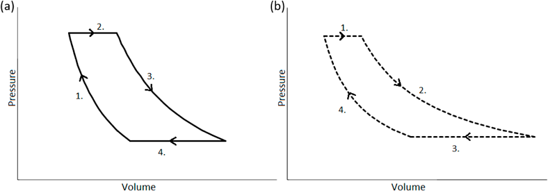
Figure 2 Pressure-volume diagram for a system comprised of a small packet of working fluid (a) in the stack of a SWR (adiabatic compression, isobaric heat expansion, adiabatic expansion, isobaric heat release); and (b) in the regenerator of a TWR (isobaric heat absorption, isothermal expansion, isobaric heat release, isothermal compression). Both graphs generated using an idealised construction of data to model processes described by the literature [8,12]. Each process is numbered corresponding with Figure 1.
1.2 Efficiency Equations
Cooling load, Qc, is a measure of the effective cooling power (in Watts) delivered by the TACS. Together with the acoustic input power WIN (in Watts) it can be used to determine the Coefficient of Performance (COP) – a dimensionless, fractional expression of a refrigerator’s efficiency given in equation 1.
A more useful value for judging the efficiency of refrigeration devices can be obtained by comparing measured values of the COP to the theoretical maximum cooling efficiency, COPC (as determined by the Carnot equation for an ideal refrigerator). This value is known as the Coefficient of Performance relative to Carnot, or COPR [5]; these parameters are described in equations 2 and 3, where TC is the temperature at the CHX, and TH is the temperature at the AHX.


2. Methods
2.1 Data Selection
In selecting data for meta-analysis, several journal search criteria were used to ensure the use of relevant and current information. Searches were conducted using databases such as Scopus, ScienceDirect, as well as the UTS Library. Keywords used include ‘thermoacoustic refrigeration’, ‘thermoacoustic cooling’, ‘parallel plate stack’, ‘Prandtl number’ and ‘working fluid’. Data sources involving thermoacoustics were selected to be recent (published from 2000 onwards) in order to obtain data that is modern, as the field of thermoacoustics has been developed for several decades. The purpose of this study required that contemporary experimental designs and data be considered for analysis. Due to a lack of consistency across the literature in the selection of components, parameters and overall structural schematics of TACS, parameters such as input frequency/power, mean pressure and system dimensions were not considered for the purposes of comparison within this study. The data recorded over a broad spectrum of experimental TACS designs focuses only on parameters pertaining to common components, such as the working fluid and (in standing-wave cooling systems) the stack. All data collated for analysis within this study was accumulated based on these axioms.
2.2 Data Analysis
Within this set of data, we have considered the optimisation of both effective cooling load and efficiency through COPR. A comparison of experimental data over a variety of designs allowed the influence of unknown and uncontrolled variables to be reduced. It should be noted that many of the data values used in the vertical axes of figures 3-5 had to be interpolated from multiple graphical data sources, using several physical measurements and confirming values using the program ImageJ [15]. This approach was required due to the lack of raw and tabulated data available in this field of commercial and industrial interest. Each of the figures 3-5 were constructed using a collation of previously unlinked data obtained from several researchers and confirmed for both accuracy and validity through comparison with other published values.
3. Results and Discussion
3.1 Spacing of Parallel-Plate Stacks
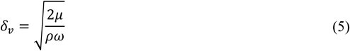
Stack plate spacing is a key parameter which greatly influences the performance of any thermoacoustic system due to its interactions with the working fluid. The parallel plate design discussed in this paper, was demonstrated to be a popular choice amongst the literature due to its manufacturability and functionality [4,6,8,12,16-20]. Hence the spacing is discussed in terms of the parallel plate design. Unlike other stack spacing geometries (pin array or honeycomb), the height between two parallel plates 2y0 is utilised, which is equivalent to half the hydraulic radius rh = y0 [16]. The hydraulic radius is the traditional measurement ratio of the stack’s cross-sectional area with respect to the perimeter of the gas channel [16,17,21]. The spacing of the plates is linked to two physical properties, thermal penetration depth and viscous penetration depth. Thermal penetration depth quantifies the thermal energy released to the plates as the gas parcels flow through the stack. The viscous penetration depth quantifies the viscous losses due particle movement in the region. Thermal penetration depth δk and viscous penetration depth δv are given in equations 4 and 5 [16,22], where k is the thermal conductivity of the gas, ρ is the density of the gas, cp is the isobaric specific heat per unit of mass, ω is the angular frequency of the sound wave and μ is the working gas dynamic viscosity.
Due to the channels created by the parallel plates, blockage ratio (BR) is implemented to account for the flow of the working fluid. Alternatively known as the degree of porosity, the blockage ratio is given by equation 6 and is equal to the proportion of open channels to total cross-sectional area in the stack [16], where l is half the thickness of a parallel plate and BR is the blockage ratio.

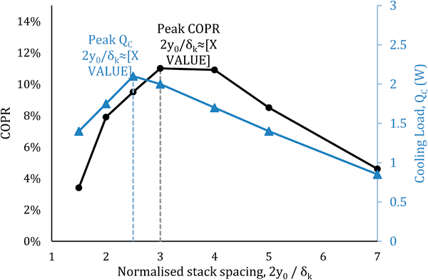
Figure 3 COPR (%) (black; leftmost vertical axis) and cooling load in W (blue; rightmost vertical axis) against normalised stack spacing 2y0/δk (the distance between plates in a parallel-plate stack scaled by the thermal penetration depth), constructed based on data from Tijani [21]. The graph peaks occur at 2y0/δk for QC and between values of 3 < 2y0/δk < 4 for COPR, a result supported across the literature [6,12,18,23].
The literature suggests that the optimal plate spacing, is reliant on the thermal penetration depth δk which was reported to be between 2δk and 4δk [12,16,21]. From the data collected, depending on the goal of the thermoacoustic system, the optimal spacing was suggested to be between 2.4δk to 2.5δk for maximum cooling output [6,12,16,18,21,23] and 3δk to 4δk for maximum COPR [12]. The reason for the difference in optimal spacing for efficiency (by COPR) and for cooling power, is that below stack spacings of around 3δk, Qc is affected more slowly than the difference in temperatures [6,21]. The ideal efficiency COPC increases rapidly, reducing COPR as demonstrated by Figure 3.
3.2 Working Fluid
The working fluid is another key parameter for any thermoacoustic system, as it is the medium in which the pressure/velocity amplitudes are transmitted and subsequently transport acoustic energy [19,24]. Thus, the properties of a given gas are paramount as an inefficient propagation of acoustic energy will result in a limited interaction with the stack. The working fluid’s interaction with the stack ultimately affects the cooling load and COPR for the formation of the temperature gradient [21,22]. Without a substantial interaction, the formation of a useful temperature gradient is not possible. The properties examined in this analysis focuses on the Prandtl number and speed of propagation of selected gases. The constituents of any selected gas play a large role in the subsequent effectiveness of the overall system; therefore, an appropriate working fluid is essential [6,23].
3.2.1 Low Prandtl Numbers and Their Effect on Efficiency
The Prandtl number of the working fluid is a dimensionless number, which quantifies forced and freed convection within a fluid, given by equation 7 [22,25], where σpr is the Prandtl number, μ is the dynamic viscosity, k is the thermal conductivity and cp is the isobaric specific heat capacity.

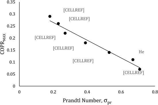
Figure 4 Optimised COPR (%) against the Prandtl number σpr of the working fluid, constructed based on data taken from Herman and Travnicek [6], in which other relevant variables are optimised and held constant between tests of various working fluids including air, helium, and noble gas mixtures of specified ratios. The graph displays a declining trend for COPR with increasing Prandtl number.
The effect of the Prandtl number on the working fluid, details the diffusivity of the gas and indicates at what rate particles may disperse throughout a given space [25]. The lower the Prandtl number, the more concentrated the particles become, as their rate of dispersion lessens. Therefore, the gas parcels can absorb/release thermal energy more efficiently, due to an approximately uniform interaction with the stack. However, it has been suggested that smaller Prandtl number values, do not necessarily correlate to a larger cooling load [6,22,26]. Herman and Travnicek [6] examined several different combinations of helium and other noble gases such as xenon. The lowest Prandtl number recorded in the study, a helium-xenon mixture (He 62%, Xe 38%), yielded a value of σpr=0.18, which is significantly smaller than the value of helium σpr =0.67. However, the maximum cooling load of pure helium was significantly higher according to Herman and Travnicek [6].
This demonstrated by Figure 4, as the lower Prandtl number corresponds with an increase in COPR, which subsequently suggests a decrease in the maximum cooling load. This result is supported by other research groups including Yazaki, Biwa and Tominaga [10] and Tasnim, Mahmud and Fraser [23].
3.2.2 Speeds of Sound and Their Utility
The propagation of the standing wave through the stack must also be accounted for, as lower speeds of propagation appear to have a counterproductive effect on the maximum cooling load of the system [6,21,27]. This may be attributed to speed of propagation scaling with other thermophysical properties such as diffusivity [6,25]. However, a lower propagation of speed also leads to less viscous losses, which in turn has been demonstrated to increase the COPR [21,27]. Similar to the optimisation of stack spacing, the working fluid will also have to be chosen with consideration to the aim of that system. In other words, deciding whether the optimal cooling load or optimal COPR is more desirable for that system, as increasing/decreasing the speed of propagation will affect the noted outcomes [11,27]. This is reflected within the literature, as the two most prominent working fluids employed are air and helium. The sound wave propagation speeds in these gases are 362.9 ms-1 and 1054.4 ms-1 respectively at a temperature of 300 K. However, despite the viscous losses incurred at higher speeds of acoustic propagation, helium or a mixture of helium and other noble gases still yield greater outcomes overall [11,21,23,27]. The manipulation of the plate spacings between the discussed boundaries will ultimately limit the effects of viscous losses; this makes helium a more viable.
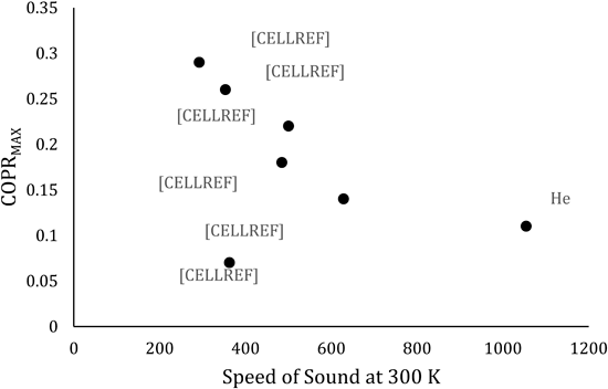
Figure 5 Optimised COPR (%) against the speed of sound propagation in the working fluid, constructed based on data obtained from Herman and Travnicek [6], in which other relevant variables are optimised and held constant between tests of various working fluids including air, helium, and noble gas mixtures of specified ratios.
In Figure 5, the graph displays a loosely declining trend for COPR with increasing speed of sound propagation for the noble gases; however, it also shows that air, whilst having a relatively low speed of sound, returns lower resulting COPR. This is likely due to the more prominent influence of other working fluid variables in air, such as a much lower thermal penetration depth and higher Prandtl number [6,27].
Consideration of the points raised in the literature, in conjunction with the analysis of figures 3-5, suggests helium or a mixture of helium with heavier noble gases, to be the most optimal working fluid. These factors have led to its repeated use by many researchers, forming a substantial basis on which the maximum cooling load and COPR of a TACS design were calculated [16,21,27]. The fact that the working fluid is not consumed is additionally beneficial to the use of both pure helium, and more expensive noble gas mixtures.
3.2.3 Specific Heat Ratio - A Factor for Further Consideration
The ratio of specific heats for a given working fluid may also be considered due to their prevalence throughout the literature. Specific heat ratios are not explicitly investigated by other research groups, though their contribution to the transfer of heat energy and use as a parameter should not be ignored. An example of this can be observed in equations 4 and 7, each of which uses cp as a parameter. The ratio of specific heats, γ, is expressed as γ = cp/cv where cp and cv are isobaric and isochoric specific heat capacities, respectively [6,22]. The links between this ratio and Prandtl number, as well as the thermal penetration depth δk,suggests the specific heat ratio may have a larger impact on the system than is currently understood. Although the revised literature does not state an ideal specific heat ratio, it is repeatedly inferred that values of γ like that of helium may be optimal [4,6,16,21-23,26-28]. Further investigations into the field would prove beneficial, as the specific heats (isobaric or isochoric) are a prevalent variable throughout the literature.
4. Conclusions
This meta-analysis explored the impacts of parallel plate spacing and working fluids, detailing the respective key constituents that influence the cooling load and COPR. This study used this data to draw conclusions based on what will ultimately optimise the temperature differential and energy efficiency within a TACS. The plate spacing analysis within section 3.1 highlighted the three parameters of thermal penetration depth, viscous penetration depth and the blockage ratio. It was determined that the viscous penetration depth and blockage ratio, hindered the thermal penetration depth, hence effecting the optimal spacing as the thermal penetration becomes less effective. The cooling load and COPR, are suggested to have optimal spacings approximately at 2.5δk and between 3δk to 4δk respectively. The upper boundary of the optimal maximum spacing of 4δk, may be attributed to larger plate spacing decreasing the number of plates, consequently decreasing the perimeter. This subsequently decreases the cooling load and COPR as fewer thermal interactions take place above spacings of 4δk. However, decreasing the plate spacing to lower values of 2.5δk, the system becomes vulnerable to higher viscous losses due to higher speeds within the plates. The use of helium or a combination of helium with other noble gases, were also determined to be the most viable working fluids due to the low Prandtl number, high speed of propagation and suspected specific heat ratio of such gases. A further qualitative investigation into the optimal value of the specific heat ratio would prove beneficial to increase the understanding of its role. If helium is selected as a working fluid, it should also be coupled with the recommended plate spacing range to limit viscous losses. This meta-study concludes that using either pure helium, or a noble gas mixture with a low Prandtl number, is optimal for the operation of TACS. The analysis further concludes that parallel plate stack spacings of approximately 2.5δk results in optimal output (cooling load), whereas spacings of 3δk to 4δk optimise the system’s efficiency (COPR).
Acknowledgments
The authors of this paper would like to thank the UTS Library staff, Dr Jurgen Schulte, Blake Regan and Brendan Boyd-Weetman for their respective contributions and guidance on this paper.
References
1. Ueno S, Sakamoto SI, Orino Y, Wada T, Inui Y, Watanabe Y. Effect of input power on cooling property of a thermoacoustic cooling system with diameter-expanded prime movers. Jpn J Appl Phys. 2016;55(7). https://doi.org/10.7567/jjap.55.07ke13
2. Sanpei M, Abe K, Hoshi Y, Ichinose M, Kawamura N, Kawasaki H, et al. Performance of resistive plate counter with non-ozone depletion freon. IEEE Nucl Sci Symp Med Imaging Conf. 1996;1(3):595–8.
3. Wu Y, Polvani LM, Seager R. The importance of the montreal protocol in protecting Earth’s hydroclimate. J Clim. 2013;26(12):4049–68. https://doi.org/10.1175/jcli-d-12-00675.1
4. Chen G, Tang L, Yang Z, Tao K, Yu Z. An electret-based thermoacoustic-electrostatic power generator. Int J Energy Res. 2020;44(3):2298–305. https://doi.org/10.1002/er.5019
5. Dhuchakallaya I, Saechan P. Design and experimental evaluation of a travelling-wave thermoacoustic refrigerator driven by a cascade thermoacoustic engine. Int J Energy Res. 2018;42(9):3059–67. https://doi.org/10.1002/er.3897
6. Herman C, Travnicek Z. Performance of Thermoacoustic Refrigerators: Cooling Load and Coefficient of Performance. Cool sound: the future of refrigeration? Thermodynamic and heat transfer issues in thermoacoustic refrigeration. 2005 Nov 18; 42: 492-500.
7. Bammann TC, Howard CQ, Cazzolato BS. Review of flow-through design in thermoacoustic refrigeration. Annu Conf Aust Acoust Soc 2005, Acoust 2005 Acoust a Chang Environ. 2005;(November):294–8.
8. Jin T, Huang J, Feng Y, Yang R, Tang K, Radebaugh R. Thermoacoustic prime movers and refrigerators: Thermally powered engines without moving components. Energy [Internet]. 2015;93:828–53. Available from: http://dx.doi.org/10.1016/j.energy.2015.09.005
9. Hou M, Wu Z, Hu J, Zhang L, Luo E. Experimental study on a thermoacoustic combined cooling and power technology for natural gas liquefaction. Energy Procedia [Internet]. 2019;158:2284–9. Available from: https://doi.org/10.1016/j.egypro.2019.01.251
10. Yazaki T, Biwa T, Tominaga A. A pistonless Stirling cooler. Appl Phys Lett. 2002;80(1):157–9. https://doi.org/10.1063/1.1431695
11. Tartibu L K, Maximum cooling and maximum efficiency of thermoacoustic refrigerators. 2015 Jun 3; 52:95–102. https://doi.org/10.1007/s00231-015-1599-y
12. Kajurek J, Rusowicz A, Grzebielec A. The Influence of Stack Position and Acoustic Frequency on the Performance of Thermoacoustic Refrigerator with the Standing Wave. Arch Thermodyn. 2017;38(4):89–107. https://doi.org/10.1515/aoter-2017-0026
13. Hou M, Wu Z, Hu J, Zhang L, Luo E. Experimental study on a thermoacoustic combined cooling and power technology for natural gas liquefaction. Energy Procedia [Internet]. 2019;158:2284–9. Available from: https://doi.org/10.1016/j.egypro.2019.01.251
14. Karagusov VI, Tyatyushkin N V., Karagusov I V. Mathematical Modeling and Computational Investigation of a Cooling System. Chem Pet Eng. 2014;50(1–2):73–8. https://doi.org/10.1007/s10556-014-9858-1
15. Rasband WS. ImageJ [Internet]. Bethesda, Maryland, USA: U.S. National Institutes of Health; 1997 [updated 2018; cited 2020 May 21]. Available from: https://imagej.nih.gov/ij/index.html
16. Nouh MA, Arafa NM, Abdel-Rahman E. Stack parameters effect on the performance of anharmonic resonator thermoacoustic heat engine. Arch Mech Eng. 2014;61(1):115–27. https://doi.org/10.2478/meceng-2014-0006
17. Amirin A, Triyono T, Yulianto M. Experimental study of thermoacoustic cooling with parallel-plate stack in different distances. IOP Conf Ser Mater Sci Eng. 2019;539(1). https://doi.org/10.1088/1757-899x/539/1/012037
18. Setiawan I, Bambang Setio Utomo A, Katsuta M, Nohtomi M. Experimental study on the influence of the porosity of parallel plate stack on the temperature decrease of a thermoacoustic refrigerator. J Phys Conf Ser. 2013;423(1). https://doi.org/10.1088/1742-6596/423/1/012035
19. Hussain MN, Janajreh I. Analysis of Pressure Wave Development in a Thermo-acoustic Engine and Sensitivity Study. Energy Procedia [Internet]. 2017;142:1488–95. Available from: https://doi.org/10.1016/j.egypro.2017.12.597
20. Raut AS, Wankhede US. Review of investigations in Eco-Friendly thermoacoustic refrigeration system. Therm Sci. 2017;21(3):1335–47. https://doi.org/10.2298/tsci150626186r
21. Tijani MEH, Zeegers JCH, de Waele ATAM. The optimal stack spacing for thermoacoustic refrigeration. J Acoust Soc Am. 2002;112(1):128–33. https://doi.org/10.1121/1.1487842
22. Tijani MEH, Zeegers JCH, de Waele ATAM. Prandtl number and thermoacoustic refrigerators. J Acoust Soc Am. 2002;112(1):134–43. https://doi.org/10.1121/1.1489451
23. Tasnim SH, Mahmud S, Fraser RA. Effects of variation in working fluids and operating conditions on the performance of a thermoacoustic refrigerator. Int Commun Heat Mass Transf [Internet]. 2012;39(6):762–8. Available from: http://dx.doi.org/10.1016/j.icheatmasstransfer.2012.04.013
24. Callanan J, Nouh M. Optimal thermoacoustic energy extraction via temporal phase control and traveling wave generation. Appl Energy [Internet]. 2019;241(January):599–612. Available from: https://doi.org/10.1016/j.apenergy.2019.01.257
25. Sheikholeslami M, Ganji DD. Nanofluid Forced Convection Heat Transfer. In Applications of Nanofluid for Heat Transfer Enhancement [Internet]. Netherlands: Elsevier; 2017 [cited 2020 May 18]. Chapter 3. Available from: https://doi.org/10.1016/B978-0-08-102172-9.00003-4
26. Elferink M, Steiner T. Thermoacoustic waste heat recovery engine: Comparison of simulation and experiment. 2019;065002. Available from: http://dx.doi.org/10.1121/2.0000978
27. Zolpakar NA, Mohd-Ghazali N, Hassan El-Fawal M. Performance analysis of the standing wave thermoacoustic refrigerator: A review. Renew Sustain Energy Rev [Internet]. 2016;54:626–34. Available from: http://dx.doi.org/10.1016/j.rser.2015.10.018
28. Yang R, Wang Y, Luo J, Tan J, Jin T. Performance comparison of looped thermoacoustic electric generators with various thermoacoustic stages. Int J Energy Res. 2020;44(2):1103–12. https://doi.org/10.1002/er.4998