PAM Review: Energy Science & Technology, Vol. 6
ISSN 2205-5231 | Published by UTS ePRESS | https://epress.lib.uts.edu.au/student-journals/index.php/PAMR/index
Optimisation of Wearable Thermoelectric Generators
A Condos1*, L Zimaras2, J Marlow3 and M Kurniawan4
University of Technology Sydney, Faculty of Science, PO Box 123, Ultimo NSW 2017, Australia
1 Alexander.P.Condos@student.uts.edu.au
2 Leo.Zimaras@student.uts.edu.au
3 Jacob.Marlow@student.uts.edu.au
4 Mutiara.Kurniawan@student.uts.edu.au
*Corresponding author: University of Technology Sydney, Faculty of Science, PO Box 123, Ultimo NSW 2017, Australia; Alexander.P.Condos@student.uts.edu.au
DOI: https://doi.org/10.5130/pamr.v6i0.1543
Citation: Condos, A., Zimaras, L., Marlow, J., and Kurniawan, M. 2019. Optimisation of Wearable Thermoelectric Generators. PAM Review: Energy Science & Technology, 6, Article ID 1543. https://doi.org/10.5130/pamr.v6i0.1543
© 2019 by the author(s). This is an Open Access article distributed under the terms of the Creative Commons Attribution 4.0 International (CC BY 4.0) License (https://creativecommons.org/licenses/by/4.0/), allowing third parties to copy and redistribute the material in any medium or format and to remix, transform, and build upon the material for any purpose, even commercially, provided the original work is properly cited and states its license.
Abstract
This meta-study explores some factors that can potentially affect the efficiency of a wearable thermoelectric generator. These include, but are not limited to; doping percentage, manufacturing technology, thermocouple length, area, use of heat spreaders, material, airflow and specific position on the human body. These specific designs and materials have been reviewed in this paper and specific variables have been proposed to ensure greater efficiency. In this meta-study, Bi0.5Sb1.5Te3 and Ag2Se are found to be the most effective materials, with PVD as the most effective manufacturing method. A broad temperature differential generates greater power output. Practically, a condition where there is a difference in temperature of more than 40K between the body and its environment in the application of wearable thermoelectric devices is unlikely. Despite this, a temperature difference below 40K, although small, is extremely feasible and would be able to enough power to keep intended wearable thermoelectric devices running at a constant.
Keywords
Thermoelectric; Seebeck Effect; Peltier; TEG; ZT; Wearable
1. Introduction
Small personal thermoelectric generators can be used to decrease the amount of power used in everyday devices such as watches, heart monitors, accelerometers, etc. Significant amount of research and studies on thermoelectric generators have been conducted over the years. Varying on their approach, designs, unique properties and efficiency. Many of the design factors such as fabrication technology tend to give different anomalies on the output power, hence affecting their performance. A broad temperature difference theoretically generates greater power output. Generally, a condition where a large difference in temperature could happen in the application of wearable TEGs in everyday life is highly unlikely. Other design options, including flexibility, number of pairs, bending cycles, and thickness highly influence the performance of this technology.
1.1 Thermoelectric Generators (TEG)
Thermoelectric generators are devices that utilise the Seebeck effect and the properties of semiconductors to convert thermal energy into electrical energy. The Seebeck effect is where the temperature difference between the top and bottom side of dissimilar semiconductors produce a voltage between them. This is because the electrons from the hotter side will seek the colder side to correct the temperature imbalance and since a voltage is simply the movement of electrons a voltage is produced.
Semiconductors are the most important part of a TEG being almost solely responsible for the conversion of a difference in temperature to usable electricity. The most common way to affect the efficiency of a semiconductor is to dope the material with different molecules at different concentrations. The efficiency of a semiconductor is determined by the ZT (figure of merit) [1] of the semiconductor. The figure of merit is simply a dimensionless measure of how efficient a semiconductor is in relation to other semiconductors. The higher this value is the more efficient the semiconductor is. The ZT is determined by the variables; Seebeck coefficient (α), absolute temperature (T), electrical resistivity (ρ) and thermal conductivity (κ), given by the equation:
The materials used for wearable TEGs have to be flexible but still able to insulate to preserve the temperature difference. However, an increase in flexibility generally implies a certain decrease in thickness, which may decrease energy output. Thus, the challenge becomes trying to increase flexibility while maximising thickness.
Insulation is also highly recommended for TEG’s as its ability to conserve heat can work on both the cold and hot sides, increasing the output by keeping the temperature difference wide. One of the properties of TEGs is thermal conductivity, which is necessary to keep low since a high thermal conductivity implies the temperature difference will decrease. Heat spreaders alleviate the issue somewhat by absorbing the heat from a larger area on the warm side and dispersing the heat on the other, increasing the temperature difference.
To be successful as a wearable TEG, the position in which the device is placed is very important. It must be comfortable but also efficient and open to an airflow.
The thickness of a wearable TEG is considered a problem so much that some may ask does it need to be any thicker than the minimum. This is where the thermoelectric thickness becomes important. If this is too short, it may impact the efficiency of the TEG as a whole similarly if it is too tall.
A high voltage and power output are the desired effect for all TEG’s. Thermoelectric generators have historically struggled to produce voltage and power output necessary to power devices. However, with more advanced materials and doping techniques, this is possible.
2. Methods
To establish the foundation on which to conduct this meta-study, an investigation was conducted to attain a greater understanding of wearable thermoelectric generators, the different factors that affect a TEG’s performance and how this technology works. Literature was searched through a number of scientific databases such as ELSEVIER, SCOPUS, Google Scholar, and Web of Science). The searches on these databases were limited to the past 10 years to ensure that the information is valid and up to date with current technology. The research was focused within 8 specific design parameters by searching with keywords (thermoelectric, generator, wearable, efficiency etc.).
A broad range of papers regarding TEGs were examined in order to find some of primary parameters that that affect the TEG’s system efficiency and therefore make conclusions as to the most efficient combinations of parameters and the maximum amount of power possible. The meta-study then included 30 scientific papers that met our criteria set for this investigation focusing on these 8 designs; electrical conductivity, thermal conductivity, number of pairs, figure of merit, thickness, airflow, heat spreaders and materials used.
3. Results and Discussion
3.1 Insulation
There is major progress in the development of flexible TEGs that create better contact with the skin, thus reducing the thermal interface resistance and increasing the temperature differential across the TEG. Although, this increase in flexibility is also faced with a decrease in thickness which may result in lower energy output.
Insulation is a possible way to prevent heat loss and maintain a temperature differential. This insulation must be flexible. Polydimethylsiloxane (PDMS) is a flexible polymer with thermal conductivity of around 0.15 W/mK [2] and has been used to insulate TEG systems and prevent heat loss although, surprisingly, the PDMS insulation does not improve affect the power output and even reduces it. This because an insulated system also blocks the airflow surrounding the TEG which lowers the temperature difference of the system. From this result, PDMS insulators or any other similar method should not be used since airflow is necessary in increasing the temperature difference in the TEG.
3.2 Heat Spreaders
Heat spreaders were found to be essential in increasing the efficiency of TEGs by increasing their ability to capture heat. Since TEGs characteristically suffer from large thermal resistance [3], extending the heat spreaders past the TEGs area would drastically increase efficiency. The bottom heat spreader helps by trapping and conducting the heat from the bottom surface (hot side of TEG), whereas top spreader plate works more like a primitive heatsink, which dissipates the heat on the cold side to reduce the temperature further. The setup of heat spreaders on a TEG can be observed in Fig. 1.
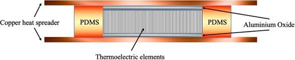
Figure 1 Simple design of a TEG with PDMS insulation and copper heat spreaders on both sides.
Copper plates of 0.13mm can be used as the heat spreaders due to its high thermal conductivity of 385 W/mK [2]. The flatness, durability and malleability of copper also make it an ideal candidate for wearable TEGs as it can be moulded easily to ergonomic shapes. With the use of a 0.4cm2 copper heat spreader, a power output of 6μW/cm2 was achieved [2] on the upper arm with no movement and a ∆T of 18.7 K. This is a 1.5 μW/cm2 increase on the power achieved with no spreader [2].
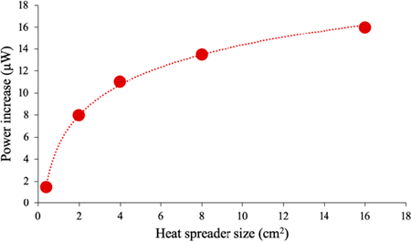
Figure 2 The effect of heat spreader area on the power produced by a TEG with area 1cm2, 20 legs and 5% fill factor.
The effect of heat spreaders on power output has also been demonstrated with a 1 cm2 TEG and with spreaders of 2cm2, 4cm2, 8cm2 and 16cm2 with 20 legs and a 2% fill factor [3]. The results from these experiments [2, 3] are summarised in Fig. 2. The initial power produced without the heat spreader was 18μW/cm2 but increased significantly with higher heat spreader area.
The data collected from literature [2, 3] shown in Fig. 2 presents a quardatic function for a power – area plot, which displays that, initially, increasing the spreader size from 0.4 cm2 to 2 cm2 increases the power output by 8 μW. Such a small increase in size (2cm2) is a small compromise for such an increase in power for a TEG. A thicker heat spreader can also increase efficiency, since with increased thickness, lateral heat flow is reduced. For uses of TEGs where there is no lack of space, a heat spread would be very effective in increasing power and could be easily integrated into common applications like watch wristbands and heart rate monitors.
Thickness of the TEG and all of its components has a large effect on its performance and efficiency. In reference to the use of heat spreaders, the in plane thermal resistance (RTH) of a spreader can be approximated using: RTH=ℓ/κA. Where ℓ is the thickness, κ is thermal conductivity and A is the cross-sectional area. From this formula it can be seen that with greater thickness, the in plane thermal resistance increases. Thermal resistance of the TEG needs to be preferably high so the temperature difference of the hot and cold side can be maintained over time without the cold side approaching the temperature of the hot side.
3.3 Airflow and Position of TEG on Body
Power generated on different parts of the skin has been reported and compared [2, 3]. It was found that the upper arm generated the highest power of approximately 20 μW/cm2 when walking at 1.4 m/s, which is where the power output became saturated and did not increase at higher speeds. In comparison, when placed on the wrist under the same parameters, the TEG only produced a max power output of 13 μW/cm2. Although, it was found that when stationary, the abdomen and chest produced larger amounts of power: 3.1-36.6 mW [4]. Although these areas are nearly always covered in clothing with reduces the heat dissipation and therefore power.
There was a much higher power output while moving than when there was zero airflow, which only produced a max of 6 μW/cm2 when placed on the upper arm. Due to the fact that airflow was found to drastically increase the power output, TEGs would be optimised during human exercise where airflow is increased as well as body temperature due to exertion. The increase in body temperature would increase the temperature differential with the environment, which is the most important aspect when increasing the efficiency of power output. In the tests performed by Hyland et al. [2], the environmental temperature measured at 18.3°C.
3.4 Thermoelement Leg Length
The power output of a TEG is also heavily dependent on leg length of the thermoelectric elements. In short, it is the height or thickness of the elements as shown in Fig. 2.
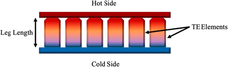
Figure 3 Schematic of a TEG system showing heat transfer across the thermocouples and demonstrating leg length.
Leg length was chosen as a variable with all other factors remaining constant. The Seebeck coefficient of the n and p-type films were 180 µV/K and 280 µV/K [5, 6]. The electrical conductivity was 3000 S/m and 1300 S/m for n and p-types respectively and the thermal conductivity was 0.25 W/m/K [5, 6]. The heat transfer coefficient was assumed to be constant and the heat conduction was assumed to be 1-dimensional. With these properties set and the parameters fixed the power output versus thermoelectric leg length was measured when ∆T=20 K [7]. The thermo- element leg length has an undeniable effect on the power generated. A steep peak was observed near 3.5 mm then a shallow drop-off after indicating that any thicker TEGs may generate less power. The largest power output of 38 μW was achieved with use of 50 thermocouples in the TEG and a leg length of 3.47 mm and area of 0.6 mm x 0.5 mm for each couple [7]. Although this is quite thin, it may not be thin enough to accommodate flexibility, so a TEG this size would work better on flatter surfaces of the body or even attached to the wrist as a watch like structure. From these figures, the power density can be calculated at 250 μW/cm2.
The way in which the legs are organised on the TEG is also very important in creating an efficient device. One way to categorise this parameter is fill factor (Av) which is given by the area of active thermoelectric material over area of non-active material [8, 9]. When this is taken into account, the results of different fill factors (Av) and leg lengths [8] can be seen in Fig 4.
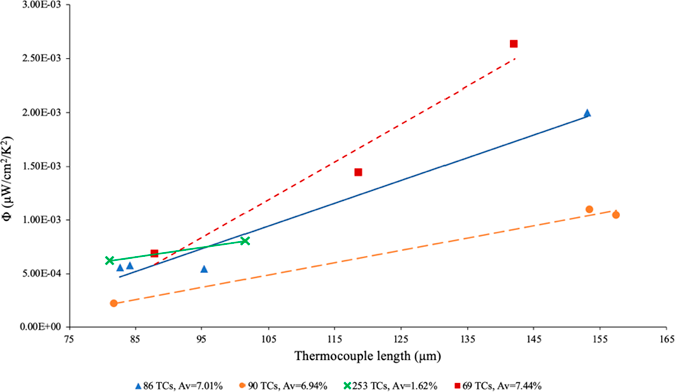
Figure 4 The efficiency (Φ) of a TEG with varying fill factor and thermocouple length.
In Fig. 4, Φ is the TEG efficiency factor, given in μW/cm2/K2. The most effective design has an Av of 7.44% and its efficiency increasers at a faster rate in comparison to the other samples. This shows that a high Av, essentially packing density, is key in achieving greater efficiency.
3.5 Flexibility and Material Composition
Material composition, in conjunction with the degree of a TEG’s flexibility, induces profoundly varying data when analysing the systems electrical conductivity, resistance and voltage/power output. The devices flexibility is inherently dependent on the material composition with n-type Ag2Se film on nylon membrane producing maximum power of 460 nW, far surpassing the 7.9 nW and 10 nW induced through the physical vapour deposition and paper-based models respectively.
Such properties have further had no adverse effect on the devices flexibility as these values were obtained at a bend radius of 4 mm. In part this is largely due to nylons characteristically excellent flexibility [10]. Additionally, the silver selenide (Ag2Se) is a porous film imbedded with Ag2Se nanograins, as such the films porosity accommodates the nylons flexibility without necessarily inhibiting and or limiting its full range of motion. Additional evidence to support the notion that flexibility with respect to bend radius has no significant impact to a systems output is represented within the paper based flexible TEG study. When plotting a system’s internal resistance against bend cycle/radius, it was evident that the increase/decrease of the resistance differed by a factor of less than 0.1 kΩ [11].
Such power outputs do not essentially lead to excellent electrical conductivity, as evident through the high throughput physical vapor deposition (PVD) Bi2Te3/GeTe and Bi2Te3/SnTe [10]. Bismuth telluride is a “near room temperature thermoelectric” (capable of attaining ZT > 1) that becomes an efficient thermoelectric conductor when alloyed with SnTe (selenium telluride) as well as GeTe (germanium telluride). Each alloyed material offers greater performances in stable and high-performance p-type semiconductor respectively. As such, the system is able to greatly outperform the Ag2Se with respect to electrical conductivity, developing an output voltage of 72 mV when doped with selenium and 42 mV with germanium. Furthermore, the systems offer power outputs of 21 mV and 7.9 mV respectively at a temperature difference 68 K.
3.6 Material analysis
In Fig. 5, as it goes to the right side of the graph, the effectiveness decreases. From the first data point, it can be seen that, for Bi2Te3 and Sb2Te, a 15K temperature difference, which is practically achievable, produces a significantly high amount of voltage output (0.010667 V/K), followed by Sb-Bi at a 30K ∆T, Bi0.5Sb1.5Te3 at 20K ∆T, Bi2(Te0.9,Se0.1)3 and (Bi0.245,Sb0.755)2Te3 at 14K ∆T. Although Al-doped ZnO and Zn-Sb at 180K temperature difference produces the highest voltage output, the difference in temperature is not practically attainable. Therefore, considering the efficiency in producing voltage output and practical uses of TEGs, a combination of Bi2Te3 and Sb2Te is the best material option.
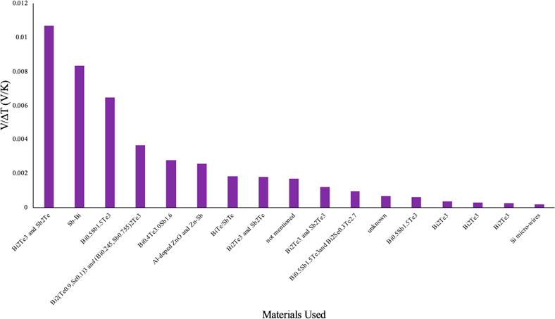
Figure 5 Voltage (V) produced per Kelvin for every material used. Data from reference number [12 - 27] were compiled and graphed to produce the plot of Voltage per 1K temperature difference versus material used.
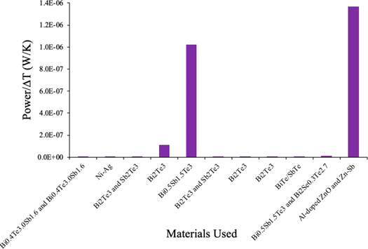
Figure 6 Power (W) produced per Kelvin for considered materials. [12 - 27]
From Fig. 5 we concluded that Bi2Te3 and Sb2Te is the best combination of materials considering voltage output, however this produces a significantly low power output. Bi0.5Sb1.5Te3 on the other hand produces a significant amount of power (Fig. 6) and considerably efficient in producing voltage as shown on the third bar of Fig 5. Al-doped ZnO and Zn-Sb also produces a high power and voltage, however the high difference in temperature (180K) simply is not practically attainable for wearable TEGs. Bi2Te3 and Sb2Te is an efficient material in producing voltage for this technology, the power output is extremely low. Although Bi0.5Sb1.5Te3 is not as efficient in producing voltage compared to Bi2Te3 and Sb2Te, it produces a significantly higher power. Overall, considering both aspects, voltage and power output, Bi0.5Sb1.5Te3 is the best choice of materials.
3.6.1 Paper-Based TEG systems
3.6.1.1 Paper-Based: Voltage and Power Output
The PVD TEG’s were analysed at room temperature and contained semiconductors (bismuth telluride – Bi2Te3) doped with either GeTe or SnTe (germanium telluride and tin telluride respectively). With reference to Fig. 7, it becomes evident that the Bi2Te3/Bi0.5Sb1.5Te3 device produces a linear and more predictable data set over an extended ΔT, whilst the germanium telluride doped TEG (Bi2Te3/GeTe) developed greater outliers, diverging from its voltage linearity between 25 K and 40 K, whilst exhibiting a significant increase in power output at 45 K. Though each data set varies in magnitude and linearity, they all reflect the profoundness of the Seebeck effect in developing an optimal device. The trends reveal that each device is capable of sustaining greater outputs in voltage and power with an increase in temperature difference between the two opposing plates. With the Bi2Te3/Bi0.5Sb1.5Te3 voltage and Bi2Te3/GeTe having the steepest curves showing that they produce more voltage/power with lower temperature differences As seen in Fig. 8, Power and voltage appear to be interrelated as they each have inverse effects upon the other. Analysing the voltage behaviour of high-performance silver selenide against flexible paper-based TEG [10, 11] recognises that achieving a maximum peak in either property will inversely correlate to a diminished reading in the opposing characteristic.
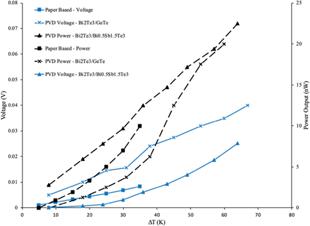
Figure 7 Dependence of Voltage (V) and Power Output (nW) on Temperature difference (ΔT) for flexible paper based and physical vapour deposited (PVD Bi2Te3/GeTe & Bi2Te3/Bi0.5Sb1.5Te3) micro thermoelectric generators. As derived from data in references [11, 28]
This behaviour is outlined in the graph as it shows the Bi2Te3/Bi0.5Sb1.5Te3 TEG producing a maximum voltage of 0.072V at 7.9nW as opposed to Ag2Se with a peak power reading 452nW at 0.0111V. Analysing the peak performance of these respective devices further reveals peak voltage of the paper device is an order of magnitude equal to 6.4 times greater than the silver counterpart, as well as the high performance TEG producing a power output 56 times greater than said paper TEG. Optimising material selection in aim to reduce such disparity in ratio of peak power to voltage would yield the most efficient TEG.
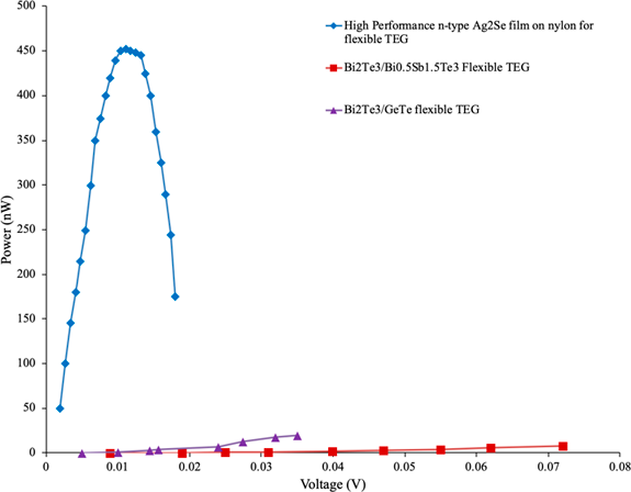
Figure 8 Power (nW) as a function of Output voltage (V) for flexible paper based and high performance Ag2Se film on Nylon micro thermoelectric generators, as derived from data in reference [10, 11].
3.6.1.2 Paper-Based: Seebeck Coefficient and Electrical Conductivity
The data attained for three devices in Fig. 9 identifies each system as having either a p-type or n-type semiconductor as their base material by subdividing the Seebeck coefficients into negative and positive data sets, with n-type and p-type semiconductors yielding negative and positive Seebeck coefficients respectively. The graphs depict a linear increase in the respective Seebeck coefficients with respect to temperature (a phenomenon also expressed within Fig. 7). Such behaviour in the materials physical properties displays the thermodynamic properties at play within the system by recognising greater Seebeck coefficient absolute divergence from zero (both negative and positive direction) encourages greater electrical conductivity.
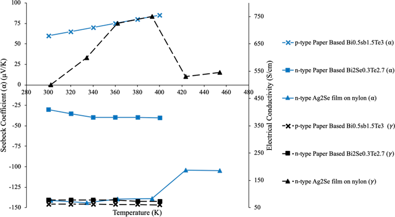
Figure 9 Seebeck Coefficient and Electrical Conductivity Dependence Temperature (K) for flexible paper based and high performance Ag2Se film on Nylon micro thermoelectric generators, compiled with data from [10, 11].
This phenomenon is further expressed by analysing the silver selenide (Ag2Se) film and nylon base TEG [10, 11]. This yields a maximum coefficient of -150 μV/K between temperatures 300 K to 400 K; the silver selenide devices induce a peak conductivity in excess of 750 S/cm. The data obtained is orders of magnitude greater than both p and n-type paper-based readings (maximum 62.5 S/cm and 78 S/cm respectively) due to its material properties (selenium and silver yielding the greatest Seebeck and electrical conductivities of any element). Inversely the sudden 220S/cm drop in electrical conductivity from 393 K to 423 K further highlights the interdependence of a materials coefficient and electrical conductivity as the phenomenon was accompanied by an uncharacteristic decline of 34 μV/K Seebeck coefficient, unique to the Ag2Se device, not evident in the paper-based device.
3.6.1.3 Seebeck Coefficient and Electrical Conductivity for composite and paper-based materials
The data analysed within Fig. 10 depicts inherent thermoelectric properties; exhibiting the apparent disparity in the Seebeck coefficient/electric conductivity in relation to specific materials. All materials analysed share a base chemical construct comprising of Bi2Te3 (Bismuth Telluride) [11], Both the polymer and polyester fabric composites fail to develop electrical conductivities within range of the fiberglass and paper counter parts as fabrics are inherently poor electron conductors. Though their Seebeck coefficients indicate they are excellent potential TEG semiconductors, they fail to accurately reflect their inherent suitability. The fibreglass and paper composites exhibit conductivity levels that unmistakeably surpass the fabric composites, and so are far superior at operating in conditions exhibiting a restricted temperature difference (ΔT).
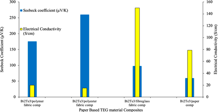
Figure 10 Seebeck Coefficient and Electrical Conductivity at 300K for thermoelectric materials and composite fabrics for paper based micro thermoelectric generators, compiled from [11].
3.6.1.4 Seebeck Coefficient and Thermal Conductivity for composite and paper-based materials
Figure 11 shows that, although the fabric composites display an excellent Seebeck coefficient with respect to the paper composite [11], the thermal conductivity also jumps to significantly higher values. This property proves undesirable in TEG design and optimisation as a greater thermal conductivity indicates a greater difficultly in upholding a temperature difference across the TEG device. A balance between high Seebeck coefficient, high electrical conductivity and low thermal conductivity must be found in order to produce an effectively efficient TEG. As such it is recognised that the fiberglass followed by paper composite yields the most efficient results, with the fibreglass semiconductor exhibiting tremendous electrical conductivity (with relation to composite counterparts) as well as the paper composite displaying the highest peak difference between thermal conductivity and Seebeck coefficient.
3.7 Semiconductor Efficiency
3.7.1 Figure of Merit
The efficiency of a semi-conductor’s ability to convert energy from one form to another is determined by its figure of merit (ZT). The formula to determine ZT was given in the Introduction. Therefore, to increase the efficiency of a semiconductor the values in this formula should be set up in order to increase ZT, in other words, it is necessary to increase the Seebeck coefficient and temperature difference and decrease electrical resistivity and thermal conductivity.
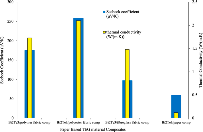
Figure 11 Seebeck Coefficient and Thermal Conductivity at 300K for thermoelectric materials and composite fabrics for paper based micro thermoelectric generators, compiled from [11].
The most promising area of research on improving the figure of merit in semiconductors is by doping the material. In Fig. 12, the semiconductor material used is given by . Where, y (doping percentage) is the percentage of the atoms in the molecular structure for example if y = 0.25 then for every 4 Pb atoms and 3 Te atoms, there would be 1 Se atom.
| Figure of Merit at Temperature (K) | ||||||||
|---|---|---|---|---|---|---|---|---|
| 300 K | 375 K | 475 K | 575 K | 675 K | 775 K | 875 K | ||
| Doping Percentage (y) | 0.15 | 0.1 | 0.2 | 0.5 | 0.8 | 0.8 | 1.2 | 1.1 |
| 0.25 | 0.1 | 0.225 | 0.6 | 1.1 | 1.1 | 1.45 | 1.2 | |
| 0.75 | 0 | 0.05 | 0.2 | 0.4 | 0.4 | 0.75 | 1.4 | |
| 0.85 | 0 | 0.05 | 0.15 | 0.3 | 0.3 | 0.7 | 1.7 | |
| 0.95 | 0 | 0.05 | 0.1 | 0.25 | 0.25 | 0.6 | 1.45 | |
As the material undergoes P-type doping, the ZT peaks when y = 0.25 or 12.5% of the material being made of the doped atom, before decreasing in all cases until 875 K. At some point between 775 K and 875 K, the ideal y shifts from 0.25 to 0.85. This implies that between those temperatures, y gradually shifts higher. Therefore, the ideal amount of doping is around 0.25 up to around 875K where a y of 0.85 would be more effective. The exact nature and rate of this increase has not been examined. For future research it would be practical to determine if this is constant in all p-type doping or if it is specific to the material; if it is, then what is the exact doping percentage that is most efficient at each temperature for other materials.
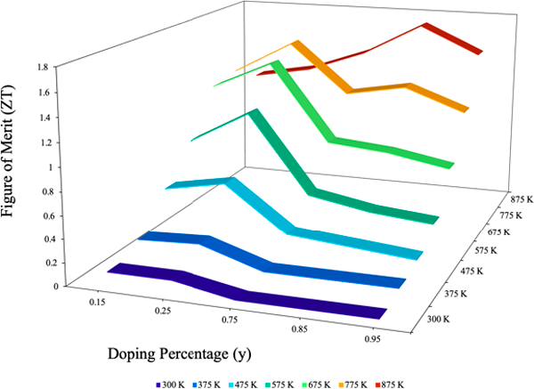
Figure 12 The figure of merit (ZT) measured at different temperatures and doping percentages, using the data from Table 1.
3.7.2 Increasing the Seebeck Coefficient
The bulk structure’s Seebeck coefficient maxes out before concentration 1017cm-3 [30, 31]. Theoretically, if the ZT maximum is at 25% and the Seebeck coefficient’s maximum is before 1017 cm-3. Then logically 25% doping comes before 1017 cm-3 concentration of the doped atom. Research to determine the exact concentration of doping that will maximise the Seebeck coefficient should be done.
3.7.3 Decreasing the Electrical Resistivity
As the material is doped the electrical resistivity decreases. However, since the Seebeck coefficient also decreases [30,31], there must be a point at which the benefit of doping for a decreased electrical resistivity is of-set by the decrease to the Seebeck coefficient. This is likely the reason for the decrease after y = 0.25 in Fig. 12. Therefore, methods to decrease the electrical resistivity without excessive doping should be investigated.
4. Conclusion
The data pertaining to flexible paper based, physical vapour deposition (PVD) and sliver selenide film deposited on nylon thread thermoelectric generators recognises the interdependence of the Seebeck coefficient with respect to the TEG’s efficiency. The findings demonstrate elevated Seebeck coefficients do not always translate to excellent electrical conductivity (as shown with fabric/ polymer composites). Their Seebeck coefficients reflect their increased thermal conductivity. Such properties hinder TEG efficiency, as a higher thermal conductivity inhibits the devices ability to maintain an optimal temperature disparity. Subsequently, the data shows semiconductors doping charge (p-type or n-type semiconductor) have no inherent effect upon the electrical conductivity, only their coefficients convergence from zero impacts the conductivity, with greater divergence yielding higher conductivity. The silver selenide TEG utilises the highest electrically conductive material (Silver) doped with the highest Seebeck coefficient element (selenium) to yield power and electrical conductivity far surpassing all other devices analysed at the expense of a subpar voltage output.
The PVD devices produced the most admirable data by which the voltage and power increase relatively proportionally to one another. In contrast, the Ag2Se film on nylon failed to produce a proportional voltage and power increase over a set temperature. As such the PVD TEGs operate at an optimal efficiency by producing the most predictable output values over a given temperature range. Substituting silver selenide into said device shows promise as a greater alternative. Fiberglass semiconductor composites show a capacity to function as a viable material for wearable TEG’s as they exhibit a relatively good Seebeck/thermal conductivity disparity whilst also demonstrating excellent electrical conductivity. Moreover, substituting the Bismuth telluride/fiberglass composite (Bi2Te3) for silver selenide would likely greatly benefit the devices overall performance and hence efficiency. Given the devices size and lack of moving parts, an optimal fiberglass Ag2Se composite PVD TEG could have possible application when interwoven in active sports-wear, harnessing ΔΤ between waste body heat and the external environment to operate small-scale devices such as pedometer, heart rate monitor or possibly speedometer. Additionally, the traditional PVD device (substituted with Ag2Se) applied directly to the body in particular the chest or upper arm, would more than likely yield the same parameter outputs. However more quantified research is still needed to truly optimise small scale wearable TEG’s.
When comparing Bi0.5Sb1.5Te3 to (Bi2Te3 and Sb2Te) and Sb-Bi; (Bi2Te3 and Sb2Te) and Sb-Bi produce greater voltage but Bi0.5Sb1.5Te3 produces around 4900 times more power. This suggests that it could be safe to say that Bi0.5Sb1.5Te3 is the best material choice for TEGs owing to its significant power output and efficiency in producing voltage with practically attainable change in temperature.
The semiconductor of a TEG can have its efficiency improved in two main ways an increase in the Seebeck coefficient and a decrease in electrical resistivity. The doping that gives the maximum efficiency is around 12.5% of the semiconductor material doped.
It was found that heat spreaders are very effective in increasing the power output of a standard TEG and that a heat spreader even of only 2 cm2 would be a worthwhile addition to a TEG to increase the power output by 8μW. The upper arm is also determined to be the most effective position on the body for a wearable TEG when there is movement at around 1.4 m/s, generating 20 μW, with a less effective material. This movement was very clearly necessary to increase airflow, which increased the ∆T, therefore increasing power. A fill factor of around 7.44% was also determined to be the most efficient in generating power, with longer leg length increasing the efficiency as well. Combining these factors while using Bi0.5Sb1.5Te3 or Ag2Se would be very effective in producing an extremely efficient wearable TEG
Acknowledgments
We would like to thank Dr. Jurgen Schulte, Liam Martin, Joshua Pritchard and Blake Regan for guidance and help in the writing of this meta-study and fellow Energy Science & Technology students and the University of Technology Sydney for help in the peer-review process.
References
1. Snyder GJ, Snyder AH. Figure of merit ZT of a thermoelectric device defined from materials properties. Energy & Environmental Science. 2017;10(11):2280-3. https://doi.org/10.1039/c7ee02007d
2. Hyland M, Hunter H, Liu J, Veety E, Vashaee D. Wearable thermoelectric generators for human body heat harvesting. 2016;182:518–24. https://doi.org/10.1016/j.apenergy.2016.08.150
3. Suarez F, Nozariasbmarz A, Vashaee D, ÖZTürk MC. Designing thermoelectric generators for self-powered wearable electronics. Energy & Environmental Science. 2016;9(6):2099-113. https://doi.org/10.1039/c6ee00456c
4. Siddique AR, Mahmud S, Van Heyst B. A review of the state of the science on wearable thermoelectric power generators (TEGs) and their existing challenges. Renewable and Sustainable Energy Reviews. 2017 Jun 1;73:730-44. https://doi.org/10.1016/j.rser.2017.01.177
5. Madan D, Wang Z, Chen A, Juang RC, Keist J, Wright PK, Evans JW. Enhanced performance of dispenser printed MA n-type Bi2Te3 composite thermoelectric generators. ACS applied materials & interfaces. 2012 Nov 15;4(11):6117-24. https://doi.org/10.1021/am301759a
6. Madan D, Wang Z, Chen A, Wright PK, Evans JW. High-performance dispenser printed MA p-type Bi0. 5Sb1. 5Te3 flexible thermoelectric generators for powering wireless sensor networks. ACS applied materials & interfaces. 2013 Nov 8;5(22):11872-6. https://doi.org/10.1021/am403568t
7. Madan D, Wang Z, Wright PK, Evans JW. Printed flexible thermoelectric generators for use on low levels of waste heat. Applied energy. 2015 Oct 15;156:587-92. https://doi.org/10.1016/j.apenergy.2015.07.066
8. Glatz W, Schwyter E, Durrer L, Hierold C. Bi2Te3-Based Flexible Micro Thermoelectric Generator With Optimized Design. Journal of Microelectromechanical Systems. 2009 Jun;18(3):763-72. https://doi.org/10.1109/jmems.2009.2021104
9. Lee G, Choi G, Kim C, Kim Y, Choi H, Kim S, Kim H, Lee W, Cho B. Material Optimization for a High Power Thermoelectric Generator in Wearable Applications. Applied Sciences. 2017 Sep 30;7(10):1015. https://doi.org/10.3390/app7101015
10. Ding Y, Qiu Y, Cai K, Yao Q, Chen S, Chen L, He J. High performance n-type Ag 2 Se film on nylon membrane for flexible thermoelectric power generator. Nature communications. 2019 Feb 19;10(1):841. https://doi.org/10.1038/s41467-019-08835-5
11. Zhao X, Han W, Zhao C, Wang S, Kong F, Ji X, Li Z, Shen X. Fabrication of Transparent Paper-Based Flexible Thermoelectric Generator for Wearable Energy Harvester using Modified Distributor Printing Technology. ACS applied materials & interfaces. 2019 Feb.
12. Francioso L, De Pascali C, Farella I, Martucci C, Cretì P, Siciliano P et al. Flexible thermoelectric generator for ambient assisted living wearable biometric sensors. Journal of Power Sources. 2011;196(6):3239-3243. https://doi.org/10.1016/j.jpowsour.2010.11.081
13. Qu W, Plötner M, Fischer W. Microfabrication of thermoelectric generators on flexible foil substrates as a power source for autonomous microsystems. Journal of Micromechanics and Microengineering. 2001;11(2):146-152. https://doi.org/10.1088/0960-1317/11/2/310
14. Yadav A, Pipe K, Shtein M. Fiber-based flexible thermoelectric power generator. Journal of Power Sources. 2008;175(2):909-913. https://doi.org/10.1016/j.jpowsour.2007.09.096
15. Navone C, Soulier M, Plissonnier M, Seiler A. Development of (Bi,Sb)2(Te,Se)3-Based Thermoelectric Modules by a Screen-Printing Process. Journal of Electronic Materials. 2010;39(9):1755-1759. https://doi.org/10.1007/s11664-010-1187-3
16. Takashiri M, Shirakawa T, Miyazaki K, Tsukamoto H. Fabrication and characterization of bismuth–telluride-based alloy thin film thermoelectric generators by flash evaporation method. Sensors and Actuators A: Physical. 2007;138(2):329-334. https://doi.org/10.1016/j.sna.2007.05.030
17. Jo S, Kim M, Kim M, Kim Y. Flexible thermoelectric generator for human body heat energy harvesting. Electronics Letters. 2012;48(16):1015-1017. https://doi.org/10.1049/el.2012.1566
18. Yang Y, Lin Z, Hou T, Zhang F, Wang Z. Nanowire-composite based flexible thermoelectric nanogenerators and self-powered temperature sensors. Nano Research. 2012;5(12):888-895. 1. https://doi.org/10.1007/s12274-012-0272-8
19. Delaizir G, Monnier J, Soulier M, Grodzki R, Villeroy B, Testard J et al. A new generation of high performance large-scale and flexible thermo-generators based on (Bi,Sb)2 (Te,Se)3 nano-powders using the Spark Plasma Sintering technique. Sensors and Actuators A: Physical. 2012;174:115-122. https://doi.org/10.1016/j.sna.2011.11.011
20. Cao Z, Koukharenko E, Tudor M, Torah R, Beeby S. Screen printed flexible Bi2Te3-Sb2Te3based thermoelectric generator. Journal of Physics: Conference Series. 2013;476:012031. https://doi.org/10.1088/1742-6596/476/1/012031
21. Kim MK, Kim MS, Jo SE, Kim HL, Lee SM, Kim YJ. Wearable thermoelectric generator for human clothing applications. In: Proceedings of the 17th international conference on solid-state sensors, actuators microsystems, (transducers eurosensors XXVII) IEEE; 2013, p. 1376–9. https://doi.org/10.1109/transducers.2013.6627034
22. Cao Z, Ruan X, Meng B, Shi C. Determination of dosimetric parameters for 125I seed source using MCNP5 and EGSnrc MC codes. He Jishu 2014;37(2):1.
23. Khan S, Dahiya RS, Lorenzelli L. Flexible thermoelectric generator based ontransfer printed Si microwires. In: Proceedings of the 44th european solid statedevice research conference IEEE (ESSDERC); 2014. p. 86–9. https://doi.org/10.1109/essderc.2014.6948764
24. Kim M, Son J, Lee H, Hwang H, Choi C, Kim G. Highly porous 3D nanofibrous scaffolds processed with an electrospinning/laser process. Current Applied Physics. 2014;14(1):1-7. https://doi.org/10.1016/j.cap.2013.10.008
25. We J, Kim S, Cho B. Hybrid composite of screen-printed inorganic thermoelectric film and organic conducting polymer for flexible thermoelectric power generator. Energy. 2014;73:506-512. https://doi.org/10.1016/j.energy.2014.06.047
26. Kim S, We J, Cho B. A wearable thermoelectric generator fabricated on a glass fabric. Energy & Environmental Science. 2014;7(6):1959. https://doi.org/10.1039/c4ee00242c
27. Fan P, Zheng Z, Li Y, Lin Q, Luo J, Liang G et al. Low-cost flexible thin film thermoelectric generator on zinc based thermoelectric materials. Applied Physics Letters. 2015;106(7):073901. https://doi.org/10.1063/1.4909531
28. Morgan KA, Tang T, Zeimpekis I, Ravagli A, Craig C, Yao J, Feng Z, Yarmolich D, Barker C, Assender H, Hewak DW. High-throughput physical vapour deposition flexible thermoelectric generators. Scientific reports. 2019 Mar 13;9(1):4393.
29. Zhang Q, Cao F, Liu W, Lukas K, Yu B, Chen S, Opeil C, Broido D, Chen G, Ren Z. Heavy doping and band engineering by potassium to improve the thermoelectric figure of merit in p-type pbte, pbse, and pbte1–y se y. Journal of the American chemical society. 2012 Jun 7;134(24):10031-8. https://doi.org/10.1021/ja301245b
30. Zide JM, Vashaee D, Bian ZX, Zeng G, Bowers JE, Shakouri A, Gossard AC. Demonstration of electron filtering to increase the Seebeck coefficient in In 0.53 Ga 0.47 As∕ In 0.53 Ga 0.28 Al 0.19 As superlattices. Physical Review B. 2006 Nov 30;74(20):205335. https://doi.org/10.1103/physrevb.74.205335
31. Neophytou N, Zianni X, Kosina H, Frabboni S, Lorenzi B, Narducci D. Simultaneous increase in electrical conductivity and Seebeck coefficient in highly boron-doped nanocrystalline Si. Nanotechnology. 2013 Apr 19;24(20):205402. https://doi.org/10.1088/0957-4484/24/20/205402