PAM Review: Energy Science & Technology, Vol. 5
ISSN 2205-5231 | Published by UTS ePRESS | https://epress.lib.uts.edu.au/student-journals/index.php/PAMR/index
A Meta Study on the Implications of Thermoelectric Generation on Hybrid Photovoltaic Systems
Jamison Ghinis1 and Clifford Leslie2*
1 University of Technology Sydney,15 Broadway, Ultimo NSW 2007; E-Mails: 12960276@student.uts.edu.au
2 University of Technology Sydney,15 Broadway, Ultimo NSW 2007; E-Mails: 11709134@student.uts.edu.au
Corresponding author: Clifford Leslie, University of Technology Sydney,15 Broadway, Ultimo NSW 2007; 11709134@student.uts.edu.au
DOI: http://dx.doi.org/10.5130/pamr.v5i0.1499
Citation: Ghinis, J. and Leslie, C. 2018. A Meta Study on the Implications of Thermoelectric Generation on Hybrid Photovoltaic Systems. PAM Review: Energy Science & Technology, Vol. 5, pp. 104-118. http://dx.doi.org/10.5130/pamr.v5i0.1499
© 2018 by the author(s). This is an Open Access article distributed under the terms of the Creative Commons Attribution 4.0 International (CC BY 4.0) License (https://creativecommons.org/licenses/by/4.0/), allowing third parties to copy and redistribute the material in any medium or format and to remix, transform, and build upon the material for any purpose, even commercially, provided the original work is properly cited and states its license.
Abstract
The focus of this paper is a meta-study analysis of the efficiency of hybrid thermal and photovoltaic (PV) energy systems and how various materials and specific temperature ranges for thermoelectric (TE) generation can increase their efficiency. This meta- study focuses on papers obtained from ACS NANO, Scopus, Web of Science and Nature which discuss the theoretical and practical implementation of TE and PV systems, with various hybrid systems being considered. Analysed is the Figure of Merit from various hybrid TE and PV integrated systems, the effect of energy efficiency and power generation on different PV system temperatures, and output over area. The total efficiency of the hybrid system is found to have a considerable effect in all papers analysed, with an increase of 5 to 10 percent efficiency in energy output due to the thermoelectric generator (TEG) section, with this maximum efficiency occurring approximately in a 25 kelvin range [1]. A maximum output of 125 W peaks can be maintained for systems efficiently over 600 W/m2 modules, this is an up to 5 percent total efficiency increase in power output in the previously discussed 25 kelvin range [2]. The papers proposed demonstrate the more efficient implementations, potential for further study and implementation of hybrid systems within specific temperature and operating conditions.
Keywords
Thermoelectric; Hybrid; Photovoltaic; Meta Study; Thermodynamics
Introduction
PV systems have a significant issue with the decrease of efficiency with increase in temperature; these issues affect scalability and power output. TEGs have been previously used as secondary power generation to PV systems [3]. In an effort to increase the total efficiency of the collector system the Seebeck effect is harnessed to generate power from the waste heat of PV systems. This is analysed by the Figure of Merit, which is the ability of a given material to produce TE power. The Seebeck effect is the central process in TEGs and is when a temperature difference in a semiconductor produces electricity [4]. The difference in temperature in a semiconductor material causes electron/hole pairs to be created at the hot end, as heat is absorbed, at the cold ends the pairs recombine and produce heat creating a voltage potential [5].
A Figure of Merit, ZT, is the characteristic that provides a description of the performance of TE materials and systems [4]. A significant amount of effort has been made on producing materials that allow high electrical and heat conduction, using processes like super lattice structure, plasma treatment, material segmentation and nanotechnology [6]. ZT is defined by the variables that are present in the N and P type materials. These variables are the Seebeck coefficient [S], electrical conductivity [σ] and thermal conductivity [λ] and temperature [T]. These variables are related via the equation:

Equation 1: Figure of Merit [6].
The parameter ZT is dimensionless and allows comparison of the performance of a TE material, the greater the value, the greater the performance with ZT = 1 being low and ZT = 100 being large. As ZT is inversely proportional to λ this relationship demonstrates lower thermal conductivity of a material contributes to a higher performance, while a larger electrical conductivity contributes to greater performance as it is proportional [6]. Large ZT values contribute to efficiency of conversion via the relationship:
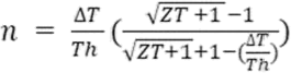
Equation 2: TEG efficiency [6].
where n = efficiency, Th is the temperature of the hot reservoir, ΔT is the temperature difference and T is average temperature of hot and cold sides.
TE materials consist of various arrays of N (doped material which consists a majority free electrons) and P (doped material that consists mainly of holes) type semiconductors [6]. A voltage potential is produced by the application of heat to one side of the NP array and a cooler sink at the other side [6].

Figure 1 TEG system diagram [7]
Heat triggers electrons to ‘loosen’ and leave their valence shell, these then travel through the hole rich P type material, then enter the shells at the cool side with some heat lost, resulting in a voltage potential, see Figure 1 [7]. Standard TE systems have a low efficiency of roughly 10% when used for power generation. These have various advantageous properties, such as no moving parts and scalable to a large degree without major waste production [6]. This makes them useful for incorporating into systems which produce heat, allowing the total output of the combined system to be increased.
PV cells consist of semiconductors containing P (filled with holes) and N (filled with electrons) doped materials and at least one electric field. Between the P and N doped materials is the junction which consists of a mix of holes and electrons. When a photon makes contact with the solar cell it will excite electrons; if the energy transmitted is greater than the valence band the excited electrons will move to the N side creating a hole which will travel to the P side creating a current through the circuit, see Figure 2 [8,9].
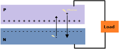
Figure 2 Operation of a PV cell [8]
Many endeavours have been made in an effort to increase the efficiency of secondary thermodynamic systems: as an accompaniment to these primary thermodynamic systems [10]. The goal of this paper is to analyse proposed integrated TE and PV systems and determine efficiency of these systems and how temperature and area of effectiveness determine their potential use, such as in hybridized solar systems.
Methodology
The method used in this meta study involved an analysis of papers from various scientific repositories. Papers discussed in our analysis had to contain specific types of information about the relationship of their TEG system and PV system, were searched using specific keywords, had to have a certain academic quality and had to provide data enough to approximate further trends outside the specific scope of the paper. The PV systems were required to connect to the TEG system it used, in series, providing the heat of the PV and temperature, the standard condition, of 25 degrees Celsius of the cold reservoir to be the factor that allowed the Seebeck effect.
The repositories that were used came from the following websites: Scopus and Web of Science being the central ones, papers from Nature and ACS NANO were also examined to fit our analysis and were included. In these repositories the search terms consisted of, ‘Thermoelectric effect’, ‘hybrid systems’, ‘Seebeck effect’ and ‘photovoltaic cell’. They allowed the reduction of potential papers to be included in the assessment of content of the paper. We focused on the effect of TEG on the PV system, because of this, PV systems values for efficiency and power output needed not to be specific but the change in the PV system when the TEG included needed to have data that was well documented. The quality of the report was analysed in reference to their citation amount. The papers that were preferred had the higher amount of citations, listed next to the references. This allowed an assurance that the used papers findings were consistent and appropriate error was considered in each.
Results
A hybrid PV-TE system is described in [11]. The module consists of a series of TE converters; the heat is generated by the primary PV system and transformed into electricity from these converters which are mounted on the heat sink, see Figure 3. The temperature difference is 50-60 degrees Celsius with a ZT equal to 1, at 300K. Using average irradiances from Utrecht in the Netherlands, and Malaga in Spain, the model is analysed with the noted efficiency from Equation 2. The TE section of this system, assuming 0.004 Z per Kelvin, is the standard for Bi2Te3 alloys [11].

Figure 3 PV/TEG system diagram [11]
Figure 4 shows that a larger Figure of Merit contributes more significantly at a higher hot temperature reservoir. Larger changes, because of the steeper gradient of line, is specifically attributed to higher Figures of merit. This relationship demonstrates the difference significantly after around 30 degrees Celsius, because of the difference from the 25 degree Celsius standard in the model. The connected PV system has an efficiency of 10.78% photon energy conversion with the module temperature being 83 degrees Celsius. With the Z value being 0.004 and a PV system at 83 degrees Celsius. Figure 4 demonstrates a ~3% efficiency of the TE system, with the original PV system having a 10.78 percent efficiency. Assuming that the energy loss is entirely heat, a total system efficiency of 13.5% is achieved for this system.

Figure 4 TEG efficiency of the system plotted against temperature of the PV module [11]
The largest PV efficiency is obtained from a free standing system having 12.5 percent efficiency, according to Figure 4 this corresponds to a 1 percent efficiency of the TE system, as it operates at 45 degrees Celsius. This demonstrates a system with a total of 13.3% total efficiency. In the modelled system presented in this paper, PV efficiency prioritisation contributed to a less efficient total system, compared with the TE system’s prioritisation because of the waste heat of the PV system degradation of the systems performance. Another model is presented in [12], a maximum of 23% total efficiency of a solar powered TEG hybrid is presented.
In this model the photons enter via a glass enclosure through the PV module and a heat conductive plate covered with a Solar Selective Absorber absorbs radiation. The heat is then conducted into the TE element, including heat lost from the SSA, then transferred to the heat sink.
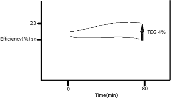
Figure 5 The efficiency of the PV & PV/TEG systems over time [12]
An initial efficiency of 22 percent is achieved by the PV system, and the efficiency of the PV cell decreases over time as heat increases in the system, see Figure 5. Application of the TEG leads to an average efficiency increase of 4%, with the waste heat powering the system and therefore a negligible decrease in efficiency over time.
In [2] there is an analysis of a PV-TE hybrid model throughout various datasets for countries in Europe, using the properties such as solar irradiation, wind speed and ambient temperature. In the model, heat loss from front glass and the rear surface have not been modelled, the modelled PV and PV/TEG system includes a glass cover, rear and front ethylene vinyl acetate layers, silicon solar cell and a tedlay layer. The EVA is used to encapsulate the Si cell.

Figure 6 PV and PV/TEG model [2]
From the graph supplied in Figure 6, it can be deduced that an overall minor efficiency decrease occurs over time as it gets less photons throughout the day. The TEG in the system prevents the systems efficiency from decreasing significantly throughout the most irradiated part of the day; higher working temperatures, similar to the previous two analysed papers are demonstrated in Figure 6. This leads to the efficiency of PV/TEG roof systems to be mainly dependant on environmental conditions unrelated to working conditions in the system, which the secondary TEG system stabilises.
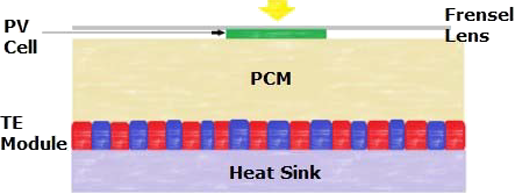
Figure 7 A diagram of the Phase Change Material hybrid (PV-PCM-TE) model [13]
A PV-PCM-TE theoretical model is discussed in [13]. Shown in Figure 7, the Fresnel lens concentrates light onto the PV cell with the increase in temperature of the PV cell being absorbed by the PCM container with consideration for minimising thermal contact resistance. The PCM is capable of absorbing additional heat as latent heat as it changes phases allowing it to assist in temperature control and produce additional power from the TE generator when its phase reverts.
As demonstrated within its results the temperature of the PV-PCM-TE system stays lower and more stable throughout the day compared to the PV and PV-TE systems. This displays a potential use to maintain an optimum temperature control for different PV-TE hybrid materials. The close temperatures the PV-PCM-TE displays with an altering temperature is a result of the good thermal conduction of the PCM as its phase change takes place at 330K. The efficiency of the PV appears greater than the PV-TE system as a result of the ceramic layer on top of the TE system acting as a thermal insulator. The energy of the PV and PV-TE systems also will fluctuate with irradiance whilst the PV-PCM-TE remains stable until towards the end of the day in which the PCM releases its stored heat, as a result of the reduction in irradiance due to the Sun setting, which goes into the TE system causing the spike in the PV-PCM-TE efficiency from TE output. This in total results in the PV with a daily efficiency of 25.55% and for the PV-PCM-TE, 26.57%. This study demonstrates that the introduction of a PCM customised to an specific optimal range for a PV-TE system can increase its daily efficiency via the storage of latent heat and create greater stability in temperature fluctuations. An integrated design consisting of a Silicon Thin-film solar (STC) cell and a TEG to create a solar-driven hybrid generation system (HGS) is designed with the intention of increasing power output in [14].

Figure 8 Design of solar cell [14]
A bowl shaped heat conductor was made consisting of a conduction, absorption and insulation layer. Copper foil was moulded to the bowl shape and stuck to the back and side of the STC (Silicon thin-film solar cell) to improve heat conduction. Black polymer tape was used on the copper foil to act as the heat absorbent. The bowls purpose is to collect additional solar radiation which is transferred to the TEG to be converted via the Seebeck effect into power. It collects direct rays from the Sun and reflected rays from the solar cell. The copper foil attached to the STC was connected to 4 TEGs and foam polymer was stuck to the back of the copper to act as the insulation. Aluminium finned heat sinks were used for heat dissipation on the cold side of the TEGs. The paper produces an increase in maximum power output of 107.9% compared to the PV system showing a clear increase in power output of a solar cell with the integration of a HGS to utilise its waste heat. With an open circuit voltage of 2.00V and short circuit current of 220mA the STC has an efficiency of 4.55%. The paper demonstrates that the maximum output of the hybrid system was higher than the STC and TEG system, in Figure 9, and that the TEG was significant contributor to the total power output.
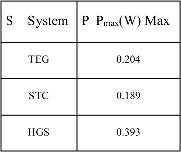
Figure 9 A summarised table of stable maximum power output [14]
The Thomson effect is considered in PV/TEG devices in [15]. The paper demonstrates the Thomson effect reduces the overall power output and efficiency, at high photon concentration ratios, as the TEG system increasing in efficiency does counteract only slightly to the overall efficiency when the PV systems efficiency drops dramatically after the heat generated by the PV module is too high, see Figure 10. The highest concentration ratio of 5 with the Thomson effect drops in power output after 700 W/m2.

Figure 10 Power output compared to Power over area, for multiple concentration ratios of a PV TEG system [15]
The paper demonstrates that the concentration ratio of the system has an effect on the PV system. The PV increasing with more photon interaction and more heat for the TEG which after a concentration of 5 reduces the PV efficiency. A concentration ratio between 1 and 5 demonstrates this linear relationship, in Figure 11. As concentration ratio increases the efficiency of the PV system decreases, but this allows the power output to increase and more heat is being put into the TEG which allows a slight increase in efficiency to the overall system.
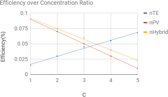
Figure 11 Efficiency over concentration ratio for modules of a PV TEG system [15]
This article demonstrated the sacrifice to system efficiency as higher power is generated. And a range of concentrator ratio is specified to maximise TEG efficiency, 3.5 to 5, which corresponds to just before the drop off in the Thomson effect generation in Figure 10.
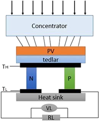
Figure 12 A diagram of the PV-TE system [16]
The model in Figure 12 (figures and diagrams for the discussed report [16] are included as open access) pertains to Figure 13 from the paper ’Analysis of the Primary Constraint Conditions of an Efficient PV-TE Hybrid System’ showing a linear relationship between the height of the TEG and the overall efficiency implying that the overall efficiency has a direct dependency on the TEG height and cross sectional area. The efficiency also appears to plateau due to an increase in cross sectional area and a trend is displayed in which, when the height is equal to the cross section it will achieve an efficiency of approximately 0.145. In Figure 14 the linear relationship between height and the cross section to produce the maximum efficiency achieved and an overall efficiency of 15% were calculated to produce the equations y=0.27x-0.11 and y=0.75x-0.48 respectively. This information can be of importance for maximising the efficiency of a TEG to be used in a PV-TE system.
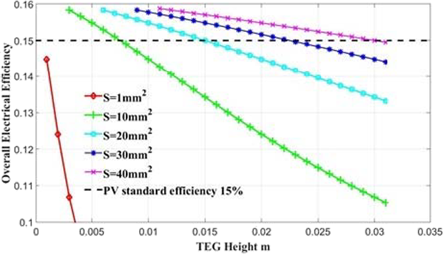
Figure 13 Graph of TEG height vs overall efficiency [16]

Figure 14 Two graphs of cold side temp of TEG vs overall efficiency with respective parameter of cross section and height [16]
The above graph demonstrates another linear relationship between the cold side of the TEG and the overall efficiency of the solar cell showing a direct dependency between TEG efficiency and its cold side temperature. It also reinforces how the efficiency is altered by the alteration of height and surface area. This decrease in efficiency is caused by the decrease in temperature difference which is a core component of the Seebeck effect though it can be noted that the decrease in height produce evenly spaced lines whilst the decrease in cross section produced lines in which parted at increased values. This could be a result of a PV-TE being dependent on the PV component with the gap difference appearing to decrease depending on the ratio of cross sections.
The paper concludes that the physical properties of the TEG significantly impact the total systems efficiency and power output. And that the temperature difference between the cold and hot side lends itself not only to total power output but the efficiency of the system because of the impact of the TEG.
The model design in [17] consists of a series of connected DSSC (dye sensitised solar cell) with a series of TEG on the bottom. The energy of light that enters the cell and isn’t lost is absorbed by the sensitised molecular within the DSSC as well as the absorber material coating the bottom of the DSSC. Remainder solar energy not converted in the DSSC is transferred as heat to the TEG. ΗD is efficiency of the DSSC, ηT is efficiency of the TEG and η is the efficiency of the hybrid system. The efficiency of the DDSC decreases with an increase of temperature whilst the efficiency of the TEG peaks somewhat in between its TL and TH temperatures and the total efficiency peaks around where the TEG would.

Figure 15 Temperature vs maximum efficiency of hybrid system with varying values of β (decreasing rate of efficiency of DSSC) and comparing efficiency of the DSSC (ηD,max) with the trend lines of the hybrid systems (ηmax) [17]
Figure 15 shows that an optimum efficiency with the hybrid is between its TL and TH which exceed the efficiency of a solar cell alone with a greater decreasing rate of efficiency per kelvin making the hybrid system last longer before returning to the trend line for a DSSC system. As seen, the greater the β is the lower the efficiency output of the TGE and thus total becomes with optical efficiency reached at lower temperatures in the study it is shown the structure parameter value increases. In feasibility evaluation [18], the schematics consist of a concentrator solar cell (CPV) which concentrates the light onto the PV cell. The CPV is designed with a thermal insulation covering it with the assumption that there is no heat transfer from the system. With an increase in solar irradiance, and therefore temperature difference, there is a decrease in the efficiency of a CPV and an increase for the TEG whilst the hybrid model experiences a slight increase showing a net gain in efficiency from the addition of a TEG. The addition of a TEG also appears to reduce the CPVs power output and efficiency. This brings the conclusion that a sole PV module is more efficient than the PV module in a PV/TEG system, but the hybrid system is overall produces more power.
3.1. A Comparative Analysis
From plotting of data [11,12], it is determined in Figure 16, that efficiency of a hybrid system increases as temperature increases. This is significant as a system without a TEG decreases efficiency with temperature. A product of the analysis is that there is a temperature at which TEG does not improve over a standard PV system, at ~ 25 degrees Celsius or standard atmospheric temperature.
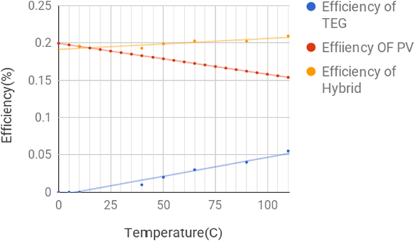
Figure 16 Efficiency of the PV system in [12] with the efficiency change when a TEG is applied in [11], this allows us to demonstrate clearly the significant effect that temperature plays in not only hybrid systems but standard PV systems
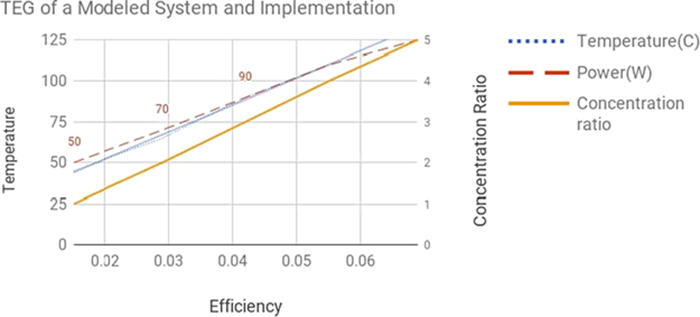
Figure 17 Temperature and power data sets for efficiency of systems [11,12]
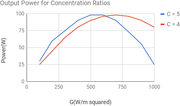
Figure 18 Power output for a PV module for different concentration ratios [15]
As determined in Figure 19 and 18, multiple concentrations of photon input, is irrelevant to total system efficiency. The maximum power outage depended on the temperature in the system. Once the system for any case of concentration ratio reached roughly 425 kelvin per module the system experienced higher output, as the TEG reached its max energy efficiency the degradation in power output by the PV module remained insignificant.
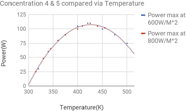
Figure 19 Power output for a PV module for different concentration ratios compared against temperature [15]
Discussion
The common thread within the analysis of the papers in this report is the importance of a TEG to compliment a PV module, and the specific parameters that allow for optimal overall efficiency both of the module and of output per area. PV systems demonstrated specifically in paper 11 and Figures 16 and 17 have a specific temperature that allows for maximum output of that sole PV system. While in paper 15 and 12, including Figures 18 and 19 this system stabilises over time from the use of TEG systems. This stems from the PV system having higher heat dissipation to allowing the PV to maintain efficiency but also, significantly, it produces power via the TEG. It is common, and discussed in the papers discussed above that PV output is the central factor in determining the power output, and consequently prioritising this optimal temperature range. The argument is made that a different temperature range should be considered, one that takes into account the efficiency of the TEG of the system. This paper determines an optimal temperature of the system, with a TEG, to be 25 - 50 degrees kelvin hotter than that optimal PV module working temperature, demonstrated in graph 19. This effect comes from the consistent linear increase of energy efficiency from the TEG module, as the TEG module efficiency increases it provides more to the total output of the system and as the PV system takes a slight dip in output because of it passing its optimal temperature the TEG systems efficiency increases compared to the PV system and it becomes more significant. The papers 9 and 12 show the trend that the difference in temperature and the consistent management of this temperature can demonstrate a higher efficiency and therefore power output over time.
Conclusion
In conclusion, this meta-analysis has revealed the significance in maintaining a temperature difference in a consistent range in any hybrid PV-TEG system, as well as the obvious benefits of having a TEG in a PV system. An efficiency increase between 1 and 5 percent can result from careful management of the temperature from a PV module and into a TEG module, such as demonstrated in 2. A suggested practical system for testing would have the properties of a management system for the temperature difference, such as in paper 13 using a PCM. While using a PV module such as from paper 15, which provides significant power output of 125 W per module. This not being the optimal PV efficiency therefore permits the TEG to use the excess heat, allowing the system as a whole to be more efficient. Concentrators such as in Figure 8 are suggested to allow the hybrid system to have power output over less area.
References
1. Vorobiev Y, González-Hernández J, Vorobiev P, Bulat L. Thermal-photovoltaic solar hybrid system for efficient solar energy conversion. Solar Energy 2006;80(2):170-176. https://doi.org/10.1016/j.solener.2005.04.022
2. Rezania A, Sera D, Rosendahl LA. Coupled thermal model of photovoltaic-thermoelectric hybrid panel for sample cities in Europe. Renewable Energy 2016;99:127-135. https://doi.org/10.1016/j.renene.2016.06.045
3. Riffat SB, Ma X. Thermoelectrics: a review of present and potential applications. Applied Thermal Engineering 2003;23(8):913-935. https://doi.org/10.1016/S1359-4311(03)00012-7
4. Geballe TH, Hull GW. Seebeck Effect in Silicon. Phys Rev 1955 May 15,;98(4):940-947. https://doi.org/10.1103/PhysRev.98.940
5. Bell LE. Cooling, Heating, Generating Power, and Recovering Waste Heat with Thermoelectric Systems. 2008 Sep 12,;321(5895):1457-1461. https://doi.org/10.1126/science.1158899
6. Zheng, Liu, Yan, Wang. A review of thermoelectrics research – Recent developments and potentials for sustainable and renewable energy applications.
7. Chen G, Dresselhaus MS, Dresselhaus G, Fleurial J-, Caillat T. Recent developments in thermoelectric materials. International Materials Reviews 2003;48(1):45-66. https://doi.org/10.1179/095066003225010182
8. Grätzel M. Photoelectrochemical cells. Nature 2001 Nov 15,;414(6861):338-344. https://doi.org/10.1038/35104607
9. Greacen C. How Photovoltaic Cells Work. Home Power 1991(23):37-39.
10. Sundarraj P, Maity D, Roy SS, Taylor RA. Recent advances in thermoelectric materials and solar thermoelectric generators – a critical review. RSC Advances 2014 Sep 16,;4(87):46860-46874. https://doi.org/10.1039/C4RA05322B
11. Sark, W G J H M van. Feasibility of photovoltaic – Thermoelectric hybrid modules. Applied Energy 2011;88(8):2785-2790. https://doi.org/10.1016/j.apenergy.2011.02.008
12. Zhu W, Deng Y, Wang Y, Shen S, Gulfam R. High-performance photovoltaic-thermoelectric hybrid power generation system with optimized thermal management. Energy 2016;100:91-101. https://doi.org/10.1016/j.energy.2016.01.055
13. Cui T, Xuan Y, Li Q. Design of a novel concentrating photovoltaic–thermoelectric system incorporated with phase change materials. Energy Conversion and Management 2016;112:49-60. https://doi.org/10.1016/j.enconman.2016.01.008
14. Deng Y, Zhu W, Wang Y, Shi Y. Enhanced performance of solar-driven photovoltaic–thermoelectric hybrid system in an integrated design. Solar Energy 2013;88:182-191. https://doi.org/10.1016/j.solener.2012.12.002
15. Lamba R, Kaushik SC. Modeling and performance analysis of a concentrated photovoltaic–thermoelectric hybrid power generation system. Energy Conversion and Management 2016;115:288-298. https://doi.org/10.1016/j.enconman.2016.02.061
16. Li G, Chen X, Jin Y. Analysis of the Primary Constraint Conditions of an Efficient Photovoltaic- Thermoelectric Hybrid System. Energies (19961073) 2017;10(1):1-12. https://doi.org/10.3390/en10010020
17. Su S, Liu T, Wang Y, Chen X, Wang J, Chen J. Performance optimization analyses and parametric design criteria of a dye-sensitized solar cell thermoelectric hybrid device. Applied Energy 2014;120:16-22. https://doi.org/10.1016/j.apenergy.2014.01.048
18. Rezania A, Rosendahl LA. Feasibility and parametric evaluation of hybrid concentrated photovoltaic- thermoelectric system. Applied Energy 2017;187:380-389.2017 /02/01;187:380-389. https://doi.org/10.1016/j.apenergy.2016.11.064