Factors Influencing the Thermodynamic Efficiency of Stirling Engines
Georgia Giannakakis 1, Hayden Ferral-Smith 2*, Joshua Taylor 3 and Joshua Wilson 4
University of Technology Sydney, P.O Box 123, MaPS, Broadway NSW 2007.
1 E-Mail: Georgia.Giannakakis@student.uts.edu.au
2 E-Mail: Hayden.Ferral-Smith@student.uts.edu.au
3 E-Mail: Joshua.G.Taylor@student.uts.edu.au
4 E-Mail: Joshua.Wilson-2@student.uts.edu.au
* Author to whom correspondence should be addressed; E-Mail: Hayden.Ferral-Smith@student.uts.edu.au
DOI: http://dx.doi.org/10.5130/pamr.v4i0.1459
Abstract: This meta-study examines the factors which contribute to Stirling engine efficiency. Working fluids should have high specific heat capacity, low viscosity and low density making noble gases the most suitable. Each different working fluid has its own optimum power output at varying pressures and temperatures. The best being Helium at 4.14 MPa and 922K. Dead volume also affects the power output of Stirling engines. Theoretical engines with zero dead volume are ideal but dead volume can occupy over 50% of the engine. Engine configuration also impacts on the efficiency of a Stirling engine. The layout of pistons and cylinders about each other can also have drastic effects on these efficiencies. Currently the most effective engine layout is the ‘gamma’ configuration, which measures 30%-32% efficient. Future research is required to produce a more efficient Stirling engines, based on the factors considered above to determine the viability of these engines as a replacement for coal and fossil fuel powered combustion engines.
Keywords: Stirling engine; efficiency; thermodynamic analysis; maximise; alpha; beta; gamma; configuration; working fluid; dead volume; Computational Fluid
![]()
Copyright 2017 by the authors. This is an Open Access article distributed under the terms of the Creative Commons Attribution 4.0 Unported (CC BY 4.0) License (https://creativecommons.org/licenses/by/4.0/), allowing third parties to copy and redistribute the material in any medium or format and to remix, transform, and build upon the material for any purpose, even commercially, provided the original work is properly cited and states its license.
1. Introduction
With limiting fossil fuel resources, and the global community becoming more aware of the detrimental environmental impacts of these as a power source, there is a compelling need for alternative energy sources worldwide [1, 2-4]. Stirling engines are a cleaner and quieter alternative to the modern combustion engines; and combined with their ability to make use of alternative fuel sources, makes them a huge attraction to modern engineers [1, 3, 4].
Robert Stirling designed the Stirling engine to try and compete with the only other engine on the market, the steam engine [4]. The defining points of a Stirling engine is that the gas or working fluid never leaves the cylinders or pipes. This also includes any other gasses such as exhaust fumes as there are no valves, unlike normal engines. This working fluid is usually air, hydrogen due to their abundance or helium due to its high efficiency in these mechanical processes [1]. The other distinctive part of Stirling engines is that the working fluid undergoes four stages. These stages, of cooling, compression, heating and expansion are known as the Stirling cycle.
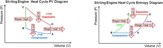
Figure 1. Showing the Stirling cycle of an ideal Stirling engine with ideal working fluids, specifically the thermodynamic processes occurring. From A-B there is compression on the working fluid but no temperature change. From B-C the regenerator heats up the working fluid but there is no change in volume. From C-D the expansion of the working fluid occurs and again there is no temperature change. From D-A the regenerator cools down the working fluid and again there is no change in volume [5].
This special cycle defines the thermal dynamic processes that the working fluid undergoes changing the pressure and turning it into mechanical energy [1, 4]. Also, the use of low friction materials prevents the need for lubricants and ensure an airtight seal. These parts are specially designed to have minimalistic normal forces, ensuring there is less fatigue and fracture on the bearings.
2. Methods
The primary research started on the 20th of March by google searching ‘Stirling engines’ to gain a brief understanding on how a Stirling Engine operates. Following this simple google search, more thorough research was conducted. Resources used within this meta-study were restricted but not limited to ‘Elsevier Science Direct’ ‘Web of Science’ and ‘Google Scholar’. There were a few keywords used to begin researching Stirling Engines. The following keywords were used: ‘Stirling engine’, ‘Stirling engine efficiency’, ‘thermodynamic analysis of Stirling engines’. These keyword terms were chosen as they succinctly spoke to the brief which was set as well as describing the subject matter of papers we were seeking. A wide range of papers were analysed before identifying some of the more significant papers regarding efficiency and structure.
On the 27th of March the idea initially was to compare the alpha, beta, and gamma with each other but soon realised how difficult it would be to compare structures of all three designs, with minimal research done specifically on just alpha, beta or gamma. Most of the information gathered looked at Stirling engines in general, or did not specify the style.
Following this, the research team looked at the gamma Stirling engine in more detail, as there were numerous articles that had stated the most recent experimental configurations had reached the highest efficiencies. A numerous amount of papers were discovered comparing different factors for Stirling engines, including looking at dead volume and working gases, but with almost no specification on the layout of engine pistons.
On the 8th of May, the initial idea of comparing the alpha, beta, and gamma Stirling engines against each other, was disregarded. The researchers began to look at other factors that influence Stirling engine power output/ efficiency. The team began to research numerous Stirling engine efficiency papers, and found that the same factors were coming up across papers.
Finally, it was decided to compare factors that influenced power output and efficiency of Stirling engines in general, as there was more information and it allowed the comparison of engine configuration on efficiency. At this stage the research team had begun to recognise recurring names in the field of Stirling engine research, such as Mohammad H. Ahmadi and Mohammad Ali Ahmadi, and considering papers written by these two, and papers they had cited for more information and to reference our current theories. It was also decided that the team split up more of the research, with each person within the group given a different database and period to research. The team decided on researching papers from Scopus, Science direct and Web of science, as these had the most success researching relevant information from these three databases. It was also decided to not research any information that dated back further then 10 years from current. This was largely because there was such a huge quantity of information on Stirling engines (due to their popularity for an extended period), that anything dating back further then this period would no longer be relevant.
Once there was a sufficient quantity of relevant information gathered, the team started to collate the date to look for any similar trends that had discovered across each of the research time frames.
3. Results and Discussion
3.1 Configuration
Stirling engines have a piston in a cylinder that drives a crankshaft. The movement of the piston is powered by a gas in a closed chamber where part of the chamber is heated and part is cooled. The gas within the closed chamber is moved between the heated and the cooled portion of the chamber by a sufficient drive mechanism. The gas will be repeatedly heated and cooled causing it to expand and contract; powering the piston [6]. There are currently three configurations of the Stirling engine; Alpha, Beta and Gamma.
The alpha Stirling engine is made up of two cylinders with distinct cylinders perpendicular to each other both attached at the same point in the crankshaft. The gas passes from the cooling cylinder through a regenerator into the heating cylinder. The cylinders are heated and cooled from external sources [7]. This engine configuration is the modest Stirling engine arrangement, although both pistons must be sealed to hold the working fluid [6].
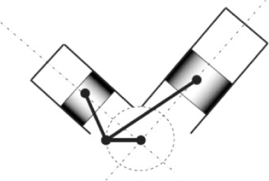
Figure 2. Alpha schematic showing the large separation of the hot and cold chambers and pistons [1].
The beta Stirling engine is the simplest form of Stirling engine, with the displaced and power pistons being contained within the same cylinder. This cylinder is separated into a hot and cold end. The displacer piston is used to pass the gas between the hot and cold ends of the cylinder, while the power piston drives the flywheel. This configuration produces the least power, with sources citing efficiency of 12%-18% [3]. This is mostly due to the heating and cooling all being contained in a single cylinder, meaning heat conduction to the cooling end and vice versa occurs quite readily.
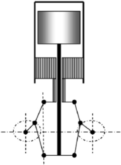
Figure 3. Beta schematic showing the linear trend of the hot, cold chambers and pistons [1].
The gamma Stirling engine is configured like the beta Stirling engine, however the displacer and the power piston are in different cylinders. The power piston is located at the cold side of the cylinder, which compresses or expands the gas being pushed back into the cylinder. Although this configuration of the engine is mechanically more efficient than the beta and alpha versions, it has higher dead volumes. Sources have cited efficiencies of 30%-32% [14].
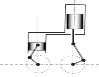
Figure 4. Gamma schematic showing the separation of hot and cold chambers, also the large amount of dead volume in the regenerator [1].
3.2 Working Gas and Pressure
The gas on which an engine operates is known as the working gas or working fluid, with several different gases able to be used in a Stirling engine. The gas used in Stirling engines should have a high thermal conductivity, a high specific heat capacity with low density and viscosity [19]. Using these factors, Martini and Clarke devised an equation to produce a capability factor for gases used as working fluids in Stirling engines.
Equation 1. The decrease of specific heat capacity and density of the working fluid improves the capability factor of Stirling engines [19].
The total volume of the working gas in the engine is determined by the displacement of the piston and is not influenced by the position of the displacer [17]. Gases with an atomic mass lesser than that of air, have a higher specific heat and gas constant. They also inhibit lower viscosity, resulting in a higher heat storing capacity [15-8]. This can be seen in the following graph which was obtained by simulation by Philip Brothers [8].
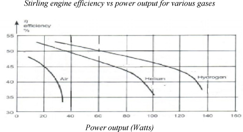
Figure 5. This graph shows the difference in efficiencies for various working gases. The graphs begin with a general linear trend that is to be expected at higher power outputs. The second linear trend corresponds to the point where the engine vibration begins to cause significant efficiency drops, as we, as inadequate heat transfer at these higher speeds. [8].
Studies have shown that higher temperatures yield higher power output [14]. A systematic study was conducted of increasing temperature and pressure of two different working fluids. This study revealed that not only did helium double the power output of the engine, but also that there is a certain pressure at which the power output peaks. This charge pressure was found to be 4bar for helium and 3bar for air [14]. When this charge pressure is exceeded, it was found to cause power output loss as well as increased engine vibration. Power output is a function of speed and torque; meaning the higher the speed and torque, the higher the engine output. Due to inadequate heat transfer after a certain engine speed, the power output begins to decrease.
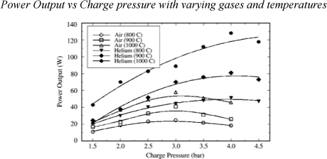
Figure 6. The above graph shows how the power output can be increased by either increasing the temperature of pressure of the working gas (to a certain peak). The lowest three graphs above do show an almost parabolic shape with a steady increase followed by a steady decrease. It is therefore assumed that the other graphs would follow this same trend (even those that may have not reached their peak over the region showed). There would therefore be an ideal pressure that would correspond to maximum power output; however, that value is not necessarily just the largest pressure achievable. [14].
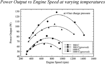
Figure 7. The above graph shows the trend for increased power for higher temperatures of certain working gases. Also, demonstrates the increase in in power output with the addition of grooves in the heat transfer surface [14].
The same study found that the addition of grooves in the heat transfer surface – resulting in a higher surface area – led to a greater power output. A surface area increase of 20% led to an increase in power output of 23% [14].
Many experiments use CFD to plot graphs and assume an adiabatic process. Figure 8 demonstrates that the increase of pressure shows a linear trend. This linear trend also improves with the decrease of temperature ratio. The efficiency and power output increase with the increase of pressure. From figure 9 we can view that 1 bar of pressure at any temperature the power is almost equal. With the increase of the hot temperature the power starts to increase.
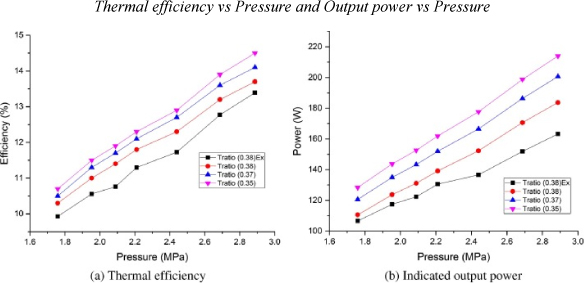
Figure 8. Showing that the increase of pressure improves both the efficiency and power output in beta type engines with an ideal gas (Examples of experimental value) [18].
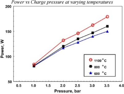
Figure 9. Showing that the increase of temperature and the increase of internal pressure at the hot end increases the maximum power output in an alpha engine with an ideal gas [5].
Figures 10 and 11, with the experimental values, further verifies that the increase in pressure increases the power output of the engine.
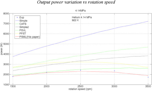
Figure 10. Comparing the values of multiple simulations of an alpha type Stirling engine with Helium as the working fluid at 2.76 MPa and 922 K [19].

Figure 11. Comparing the values of multiple simulations of an alpha type Stirling engine with helium as the working fluid at 4.14MPa and 922K [19].
3.3 Dead Volume
Dead volume is the total volume of working fluid which occupies the dead space in the engine. These dead spaces include the regenerator and transfer port. In any real Stirling engine, this dead space in unavoidable and can make up 58% of the total working fluid [14]. While dead volume is unavoidable, it should be minimised wherever possible to maximise the efficiency of the engine. Figure 13 illustrates the drop in thermal efficiency as the amount of dead volume increases. The temperature of the fluid within the dead volume should be kept at the arithmetic-mean of the input temperature and the output temperature. If the temperature is maintained, an inefficient regenerator will have no effect on the engine however a more efficient regenerator will require less heating and cooling, reducing the power needed to maintain the same power output and in turn, increase efficiency.
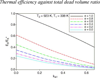
Figure 12. Comparing the dead volume ratio of a gamma Stirling engine [12]
4. Conclusions
Gamma configuration proves to be the most efficient type of Stirling engine, over alpha and beta, due to the large quantities of dead volume in alpha and the proximity of hot and cold chambers in single-cylinder beta engines. Each working fluid has shown an increase in performance with the increase of pressure and higher temperatures. From our research, it was discovered that helium was the most efficient working gas at these high pressures and temperatures (relative to the other gases) but further research is needed to determine whether using this is the most viable option due to the constantly evolving working gas mixtures. However, these extreme conditions can be quite dangerous, and therefore to design a commercially viable Stirling engine, these conditions may have to be sacrificed for a small drop in efficiency, or a safer structure of engine design. These dead volumes should be kept at a constant temperature unless a highly efficient regenerator is in use. The temperature should be the arithmetic mean of the input and output temperatures. Moving forward, more efficient Stirling engines need to be produced with the factors considered to reliably deduce whether they are a viable replacement for coal and fossil fuel powered combustion engines.
Acknowledgements
We would like to acknowledge Jurgen Schulte from the University of Technology, for his guidance and for assisting in the review of this paper. We would also like to thank our students, and the mentoring of Blake Regen and Liam Martin, for their contribution through individual peer reviews and evaluation of our paper.
References and Notes
1. Ahmadi MH, Ahmadi M, Pourfayaz F. Thermal models for analysis of performance of Stirling engine: A review. Renewable and Sustainable Energy Reviews 2017 2;68, Part 1:168-184. doi: https://doi.org/10.1016/j.rser.2016.09.033
2. Barreto G, Canhoto P. Modelling of a Stirling engine with parabolic dish for thermal to electric conversion of solar energy. Energy Conversion and Management 2017 1/15;132:119-135. doi: https://doi.org/10.1016/j.enconman.2016.11.011
3. Solar power technologies for sustainable electricity generation – A review. Renewable and Sustainable Energy Reviews 2016 3;55:414-425
4. Çinar C, Karabulut H. Manufacturing and testing of a gamma type Stirling engine. Renewable Energy 2005 1;30(1):57-66
5. Lawson, B., Heat Engines. Electropaedia 2005. Available at: <http://www.mpoweruk.com/heat_engines.htm>
6. Xiao G, Sultan U, Ni M, Peng H, Zhou X, Wang S, et al. Design optimization with computational fluid dynamic analysis of β-type Stirling engine. Appl Therm Eng 2017 2/25;113:87-102. doi: https://doi.org/10.1016/j.applthermaleng.2016.10.063
7. Cheng C, Yang H. Optimization of geometrical parameters for Stirling engines based on theoretical analysis. Appl Energy 2012 4;92:395-405. doi:https://doi.org/10.1016/j.apenergy.2011.11.046
8. Ahmadi MH, Ahmadi MA, Mehrpooya M. Investigation of the effect of design parameters on power output and thermal efficiency of a Stirling engine by thermodynamic analysis. JOUR 2016;11(2):141-156. doi: https://doi.org/10.1093/ijlct/ctu030
9. Cheng C, Yang H. Optimization of geometrical parameters for Stirling engines based on theoretical analysis. Appl Energy 2012 4;92:395-405. doi: https://doi.org/10.1016/j.apenergy.2011.11.046
10. Kongtragool B, Wongwises S. A review of solar-powered Stirling engines and low temperature differential Stirling engines. Renewable and Sustainable Energy Reviews 2003 4;7(2):131-154.
11. Alfarawi S, AL-Dadah R, Mahmoud S. Enhanced thermodynamic modelling of a gamma-type Stirling engine. Appl Therm Eng 2016 8/5;106:1380-1390.
12. Kongtragool B, Wongwises S. Thermodynamic analysis of a Stirling engine including dead volumes of hot space, cold space and regenerator. Renewable Energy 2006 3;31(3):345-359.
13. Scollo LS, Valdez PE, Santamarina SR, Chini MR, Barón JH. Twin cylinder alpha Stirling engine combined model and prototype redesign. Int J Hydrogen Energy 2013 2/12;38(4):1988-1996.
14. Cinar C, Karabulut H. Manufacturing and testing of a gamma type Stirling engine. Renewable Energy 2005;30(1):57-66. doi: https://doi.org/10.1016/j.renene.2004.04.007
15. Schmidt G. Theorie der Lehmannschen calorischen maschine. Zeit Des Vereines deutsch Ing 1871;15(1- 12):97–112
16. Çinar C, Karabulut H. Manufacturing and testing of a gamma type Stirling engine. Renewable Energy 2005 1;30(1):57-66.
17. Li R, Grosu L, Li W. New polytropic model to predict the performance of beta and gamma type Stirling engine. Energy 2017 6/1;128:62-76.
18. Almajri AK, Mahmoud S, Al-Dadah R. Modelling and parametric study of an efficient Alpha type Stirling engine performance based on 3D CFD analysis. Energy Conversion and Management 2017 8/1;145:93-106.
19. Thombare D, Verma S. Technological development in the Stirling cycle engines. Renewable and Sustainable Energy Reviews 2008;12(1):1-38. doi: https://doi.org/10.1016/j.rser.2006.07.001
20. Kaushik SC, Kumar S. Finite time thermodynamic analysis of endoreversible Stirling heat engine with regenerative losses. Energy 2000 10;25(10):989-1003
21. El-Ehwany A, Hennes G, Eid E, El-Kenany E. Development of the performance of an alpha-type heat engine by using elbow-bend transposed-fluids heat exchanger as a heater and a cooler. Energy Conversion and Management 2011;52(2):1010-1019. doi: https://doi.org/10.1016/j.enconman.2010.08.029
22. Karabulut H, Yücesu HS, Çınar C, Aksoy F. An experimental study on the development of a β-type Stirling engine for low and moderate temperature heat sources. Appl Energy 2009;86(1):68-73. doi: https://doi.org/10.1016/j.apenergy.2008.04.003
23. Unknown. Efficiency of Stirling engine and Carnot’s theorem. 2013; Available at: https://physics.stackexchange.com/questions/78915/efficiency-of-stirling-engine-and-carnots-theorem. Accessed 5/12, 2017.