Entropic Performance of Proton-Exchange Membrane through Current Density, Temperature, Pressure, Membrane Thickness and Humidity
Jeffrey Cheng 1, Jonathan Dib 2*, Sean Williams 3 and Sotaro Takei 4
University of Technology Sydney, P.O Box 123, MaPS, Broadway NSW 2007.
1 E-Mail: KwingShing.J.Cheng@student.uts.edu.au
2 E-Mail: Jonathan.F.Dib@student.uts.edu.au
3 E-Mail: Sean.D.Williams-1@student.uts.edu.au
4 E-Mail: Sotaro.Takei-1@student.uts.edu.au
* Author to whom correspondence should be addressed; E-Mail: Jonathan.F.Dib@student.uts.edu.au
DOI: http://dx.doi.org/10.5130/pamr.v4i0.1442
Abstract: The fuel cell is a renewable technology which utilizes the hydrogen fuel via oxidation to generate electricity. The development of the technology is being focused on the most effective configurations of these processes to balance availability, efficiency and capacity. A meta-study has been conducted with the aim to analyze fuel cell performance was analysed of different materials such as; Solid Oxide fuel cells, Nafion and Peresulfuric acid under a series of variables: current density, temperature, pressure, membrane thickness and humidity. The reaction kinetics at high temperatures allow for greater hydrogen and oxygen permeability and solubility but are limited by proton conductivity of membrane at high temperature. From meta-study outcome, the largest improvement in current density is achieved by improving cathode polarity and membrane permeability. Optimizing H+ ion concentration is done by increasing humidity through increased pressure.
Keywords: Fuel Cell; Proton-Exchange Membrane; Thermodynamics; Entropy; Cathode; Anode; Current Density; Membrane Thickness
![]()
Copyright 2017 by the authors. This is an Open Access article distributed under the terms of the Creative Commons Attribution 4.0 Unported (CC BY 4.0) License (https://creativecommons.org/licenses/by/4.0/), allowing third parties to copy and redistribute the material in any medium or format and to remix, transform, and build upon the material for any purpose, even commercially, provided the original work is properly cited and states its license.
Glossary:
PEMFC = Proton Exchange Membrane Fuel Cell
SOFC = Solid Oxide fuel cell
GDL = Gas diffusion layer
S = Entropy
Q = Heat
T = Temperature
η𝑐 = Conversion efficiency
η𝑒 = Efficiency loss by entropy of electrons
G = Gibbs energy
H = Enthalpy
F = Total External Body Force
I = Electric Current
1. Introduction
Renewable energy is the next big commodity around the world [1]. So much so, that since renewable technologies have the ability to store/produce energy from naturally occurring resources, investments from scientific institutions such as ‘National Science Foundation’ in the United States of America [2] and ‘Federal Ministry for Economic Affairs and Energy’ from Germany [1] into viability of renewable technologies for society, have confirmed that this is a priority in the scientific community [1, 2]. By this, renewable technologies will be more competitive and more sustainable for the environment than non-renewable technologies such as the combustion engine. Fuel cell efficiency may be the catalyst that makes electric energy viable in replacing the heat engine in the future. The fuel cell has five essential internal components that allow it to function. It includes two chambers on the outside to pump hydrogen and oxygen into the system, a core of three materials of which the two outside materials are anodic and cathodic. Furthermore in the centre, a proton-exchange membrane layer with electrolyte inside.
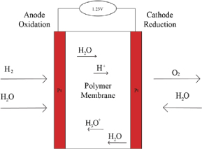
Figure 1. The Proton-Exchange Membrane (PEM)
The Proton-Exchange Membrane is the major component that makes the fuel cell work properly. On the anodic side, the chamber is filled with hydrogen gas and the catalyst layer pulls the electron from the hydrogen (H2) to form the hydrogen ions. The membrane then absorbs the hydrogen ion (hence the name ‘Proton-Exchange’) and transfers the positive ion into a chamber composed of atmospheric oxygen (O2). After the electron induces flux, it will move to the end of cathode, where finally the electron will combine with oxygen to become dioxygen (O2-) which goes on to form the by-product of H2O. The hydrogen ion from the membrane will merge into the dioxygen, and in the dioxygen filled chamber it will become H2O [3]. Heat and electrical energy are generated during this process. During its function, a single fuel cell can generate 0.6V-0.7V at 0.3-0.6A/cm2 [4], which is not enough to be useful in powering devices and technologies. The solution is to align multiple stacks against each other to acquire the voltage output needed for its function.
If the value of the entropy is greater than 0, then the process that is being conducted is an irreversible process which is how the fuel cell operates [5]. A detailed investigation into the energy flux and entropy production in the system seem to affect the efficiency of its production. The efficiency of the fuel cells are affected by other factors at the same time, Joule’s first and second law, which state the relationship between heat generated and current, as well as the independence of internal energy to volume and pressure in Ideal gases. A sample of entropy efficiency at a range of temperature, current densities, membrane thickness and pressures will produce specific entropy capacity for membrane materials we use to show functionality and weak links. This can then be used to investigate the mechanisms that dictate conductive properties, materials with a higher efficiency throughout a set of stimuli will have the best proton conductivity, methanol permeability and thermal stability.
Enthalpy released as heat determines the inefficiency or enthalpy loss of the fuel cell [6]. The conductivity of the membrane is important aspect of performance of PEM fuel cell, and to control of the conductivity in order to operate stably is the essential quality for PEM fuel cell [7]. Current density, partial pressures of reactants, anode and cathode charge transfer coefficients, leakage resistance and membrane thickness are also the factors that are used to determine efficiency of the PEM fuel cell [8]. A clear image of inefficiency in present fuel cell technology will be identified and is used as the direction for future research and development.
2. Methods
This meta-study is conducted through databases of Scopus and Web of Science, and set a limit of nothing older than 11 years; up until 2006 to utilize the most current papers, newer research having built on previous to produce the most refined data. Search keywords was ‘proton exchange membranes’ as well as ‘PEM fuel cell entropy’ and ‘PEM heat source’. Papers were sourced from a variety of journals relating to membrane science, hydrogen energy and energy research. During the research, there was no limit to the amount of papers found, as long as the papers matched our meta-study criteria which were provided by the search engine. The experimental papers that were reviewed had comparable experimental factors of the control anode and cathode, with a variety of membrane composites and experimental factors under investigation such as current density, temperature, pressure, humidity and membrane thickness. The universal tool for analysis was the thermodynamic concept of entropy while looking into the role of the dependent variables. [6]
The way that the efficiency of the fuel cell is deduced is through the concept of the non-equilibrium thermodynamics which is related to the 2nd Law of Thermodynamics [9], and goes hand in hand with entropy since it also a part of the law as well. In the fuel cell, the relationship between conversion efficiency and efficiency loss by entropy of electrons of the PEM fuel cell can be deduced as [5]:


The relation between Gibbs energy, enthalpy and entropy is [10]:

And from Eq. 2 and Eq. 3, we can find

This equation will helps analysing factors affecting the efficiency of the fuel cell, in terms of entropy. Using the data extrapolated from scientific paper graphs, performance and mechanism related to Proton Exchange Membranes are produced and are used to propose focus for further development. Graphs are chosen as the main source of information because of the large amount of data communicated and therefore useful for meta-study because of the ease of determining trends in large volumes of papers.
3. Results and Discussion
3.1. Current Density
The results that were found through the research proved the change in entropy is the defining effect on the performance of the fuel cell. Looking at the entropy production in the PEMFC.
The data from figure 2 shows an immediate increase in entropy at <20mA/cm2, and then the rate of production decreases after 20mA/cm2. The PEMFC was tested at 3 different ‘exchange current densities’ at 0.01, 0.04 and 0.07mA/cm2 can be viewed from figure 3:
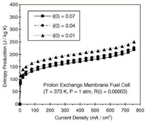
Figure 2. Entropy production at varying current densities [2]
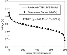
Figure 3. Voltage profile in PEMFC (T = 373K) [11]
The underlying effect that production of entropy has on the performance of the PEM fuel cell, are on the voltage output that is generated. Looking at Fig. 3, it looks like the inverse of Fig. 2; between 0-20 mA/cm2 there is a dramatic decline in voltage output, and after 100mA/cm2 the rate of the decline decreases, then increases again after 700mA/cm2.
Which aligns itself with the results from the TAP/TCS (Thin Anode for PEMFC or Thin Cathode for SOFC) model, that voltage loss is accumulated from ohmic loss. Which validates the voltage output from the entropy production [12]. Since in the past the energy loss in the fuel cell was determined by means of models from “overpotential” and “polarization” [11]. Furthermore, provides another way of measuring the voltage loss from the system [13].
The importance of this reduction of entropy in the system overall, is to reduce the resistance of the PEM from accepting the hydrogen ions to cross to the oxygen chamber to complete the process. The increase in resistance from the build-up of heat will therefore reduce the voltage being produced from the way that electrons cannot taken out of the cathode to make room for the coming electrons from the anode side [11]. Fig 2-3 shows also that reducing the current density increases the production of entropy by ‘the rapid increase of activation irreversibilities [11]’. A means of finding the optimum current density production must be deduced and tested to get the maximum voltage output from the fuel cell.
However, the production of entropy can be contributed through the chemical process involved in transferring hydrogen ions through the membrane and forming H2O [6]:

From this reversible process, the total entropy change created is shown below [6]:
Through the first half of the process; the anodic process. The change in entropy calculated by using the chemical equation [6]:


The cathodic process can be deduced by subtracting the change in entropy from the anodic process from the enthalpy to get a value of [6]:

Since the overall process is negative, this means that the chemical process is exothermic, which is one of the ways in which heat is produced in the system. As postulated by Pavelka [5] “the electrochemical reaction in the CCL (cathode catalyst layer) is responsible for most efficiency losses in the fuel cell.”
Even though the CCL layer contributes greatest to the entropy production being produced in the system, the membrane still has a significant percentage of 41.83% into the entropy being generated. Overall the production of entropy in the study conducted by Siemer, concluded that 93.5% of entropy production is in the CCL and in the membrane [13]. The analysis from Table 1 can be taken towards other ‘electrochemical systems like electrolysis cells or other fuel cell types [13],’ and therefore provides a sound bases in entropy production for fuel cells outside of PEMFC.
| Domain | Value [W/m2K] | Share [%] |
| Anode CL | 0.541 | 2.71 |
| Cathode CL | 10.312 | 51.72 |
| Membrane | 8.342 | 41.83 |
| Anode GDL | 0.188 | 0.94 |
| Cathode GDL | 0.557 | 2.8 |
The solid oxide fuel cell can be looked in the same way, but has is different in its function compared to the PEMFC. Since SOFC run at high temperatures, the change in entropy arises differently, from the way in which temperature affects the system shown in figure 4:
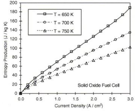
Figure 4. Entropy production in a solid oxide fuel cell [11]
SOFC become more efficient at low temperature, able to handle a higher current density as shown in figure 4. Which determines the overall voltage output produced and efficiency from the SOFC shown in figures 5 and 6:
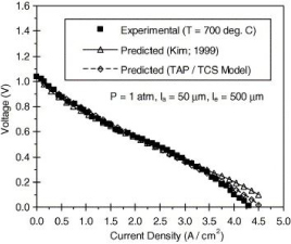
Figure 5. Comparison of SOFC voltage profile with measured data (T = 700°C) [11]

Figure 6. Voltage Profile (SOFC; T=750°C) [12]
Both figures 5 and 6 show the experimental trend of voltage against current density aligning itself well to the predicted model of the TAP/TCS Model. Since both experimental and predicted models match well, this enforces the validity of the TAP/TCS Model. Therefore confirming figure 3, both figure 5 and figure 6 cooperates well to the TAP/TCS model. [12]
[2] Using full cell and half-cell modelling, comparative polarization curves are used to predict the limitations in the system. After experimental confirmation we see the cathodic half-cell model performance is much higher than full cell model and experimental data in figure 7.

Figure 7. Polarization curve models for half and full cells [14]
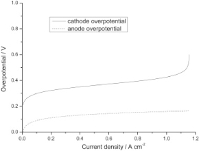
Figure 8. Anode and Cathode overpotential model [14]
The cathodic half-cell model does not account for overpotential which as shown in figure 2. Is vastly different between the anode and cathode. The results indicate that the majority of the polarization of the system comes from the cathode and therefore is the limiting factor in current density.
Since the anodic side is exothermic and the cathodic side is endothermic, if the change is entropy is equal on both ends, then that can reduce the excess heat from affecting the performance of the fuel cell. Thereby inducing a higher voltage output which can reduce the production costs of creating the fuel cell stack; making them smaller. Also, further development into the material of the proton-exchange membrane, so that a minimization of the ohmic loss can be achieved, and by doing so will reduce the friction of the ions flowing with the structure and therefore reduce the entropy generated as heat in the system.
3.2. Temperature
In this section, the results will be focused on temperature. It will be discussed ambient temperature affecting air-breathing PEM fuel cell operating with Nafion membrane. Air-breathing PEM fuel cell is fuelled by methanol or hydrogen and has high current density [16]. The reason why focusing on air-breathing PEM fuel cell is that it is sensitive and highly affected by surroundings environment, such as ambient temperature, that leads the higher ambient temperature is, the higher the cell operation temperature is [17].
Additionally, Nafion membrane is the most widely used, however operating temperature is actually limited due to membrane not getting much proton conductivity at high temperature [18]. Therefore, it is can be seen how ambient temperature and operating temperature of the cell affect the performance of the fuel cell.
Through the meta-study, M.S. Ismail et al [16] investigated efficient mathematical model of air-breathing PEM fuel cell. For air-breathing fuel cell, the effect of entropic and Joule heats are usually ignored, however it was investigated in this model [16]. In this model, data measured was surface temperature of the Cathode GDL and the cell resistance under specific conditions [16].
A polarization curve plotted [16] is the relationship between cell potential and current density (figure 9). As it is seen, under the higher ambient temperature it is operated, the lower cell potential it has.
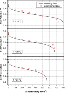
Figure 9. polarization curve of relationship between cell potential and current density [16]
Plotted above is the polarization curve of surface temperature of cathode GDL vs current density (Fig. 10). From the data, it is confirmed that the air-breathing fuel cell is affected by ambient temperature as at the same point of current density of each data, higher ambient temperature is, the higher surface temperature is with smaller current density.
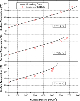
Figure 10. Polarization curve of relationship between surface temperature and current density [16]
All of the data are under the condition of different ambient temperature of 10 °C, 20 °C and 30 °C, and 40% ambient humidity.
There is more data found in [17] of ambient temperature affecting air-breathing fuel cell efficiency. This model [17] was set up with different internal structure which are with planar cathode designs and ducted cathode designs [17].
As it is shown in the graphical data, cell performance reached the highest when ambient temperature is 30 °C.
From those data, it can be said that performance of air-breathing fuel cell depends on ambient temperature, however as it is shown in figure 11 and figure 12, in terms of operating with better performance, neither too high nor too lower temperature does not provide it. In this case, ambient temperature of 30 °C is the optimal to provide better performance than either 20 °C or 40 °C.
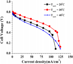
Figure 11. polarization curve of cell voltage vs current density with ducted cathode design [17]

Figure 12. Polarization curve of cell voltage vs current density with planar cathode design [17]
[19] Higher Temperature PEMFCs have greater functionality due to faster electrochemical kinetics, simpler water management, thermal stability and improved contamination tolerance. Thus research has been focused on high temperature PEMs, the electrochemical interactions allowing greater current density as temperature increases as shown in figure 13.
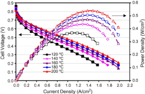
Figure 13. Current density (A/cm2) vs cell voltage (V) at temperatures 120-200 °C for Phosphoric Doped poly benzimidazole [19]
It can be noted that in Phosphoric doped poly Benzimidazole Voltage difference between 120-140°C is 49 mV whereas the voltage difference at 180-200°C is 20mV indicating that the effect of temperature on performance is more pronounced at lower temperatures and therefore there is an optimal operating temperature range rather than a constant relationship. This is due to the proton conductivity diminishing at increased temperature. [18]
3.3. Pressure
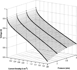
Figure 14. Variation of voltage output with current density for the fuel cell at various pressures. [15]
The operating pressure of the fuel cell gives either favourable or unfavourable condition in different situation. When a higher mole of gas is on the reactant side, with a higher pressure will boost up the reaction. Besides, high pressure helps improve water management of the cell, where increases the humidity and reduce entropy production, which will be discussed in the humidity section.
Optimum operating pressure of the fuel cell is variable to different concentration, i.e. number of mole of gas, for producing specific voltage. For example, from figure 15, the optimum pressure for air excess ratio v=2 is around 2 bar, while for v=1.8 is between 2.5 and 3 bar [20].
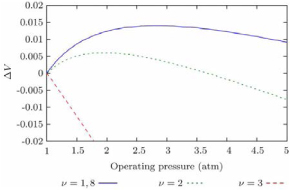
Figure 15. Net cell voltage change vs operating pressure, for different air excess ratio [20].
The pressure is not a linear factor that a higher or lower pressure will give a better efficiency for the fuel cell. But the optimum pressure is specific to temperature and number of mole of gas which have been discussed before.
3.4. Membrane Thickness
From figure 16, the entropy generation from increasing current density varies by the thickness of the fuel cell membrane. Compared within figures 16a, 16b and 16c, the 175μm thickness membrane has the highest entropy generated by the reaction, heat transfer and the overall entropy generation in the data set. The thinner membrane generate less entropy throughout the reaction, so the entropy generation varies directly from the membrane thickness of the fuel cell.
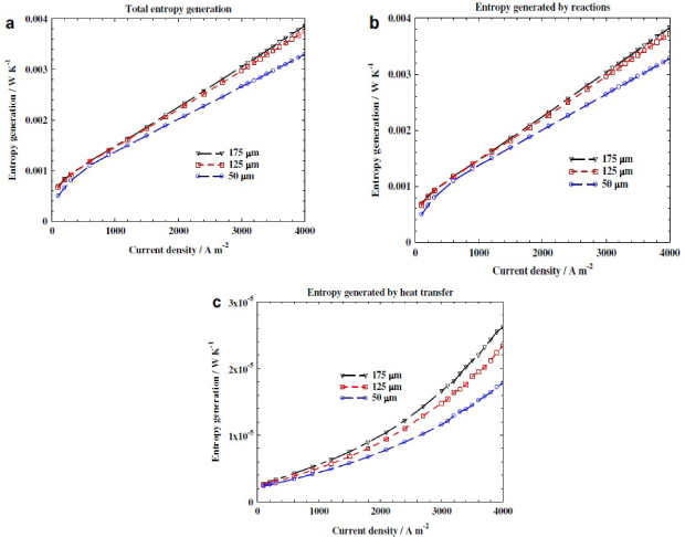
Figure 16. Entropy generation rates with different thickness electrolyte membranes: (a) total entropy generation rate; (b) entropy generated by reactions; (c) entropy generated by heat transfer [21].
This is because the thickness of membrane has different mass transfer resistance to the water back flow, where thinner membrane has a lower resistance. The water crossover rate within the membrane will be increases, hydrogen ions transmission is more efficient [21]. As the concentration of hydrogen ions is increased, the reaction rate increases, thus boost up the efficiency of the fuel cell.
Despite the thickness of membrane, the changing in current density through the fuel cell membrane will also change the entropy generation. As shown in fig. 1, the entropy generated by the fuel cell with increased current density has an exponential increase trend for the heat transfer process. This shows that with a higher current density, the heat wasted will be much higher, compared with a lower current density. The reason has been discussed on the current density section.
By Eq. 4 from method section, the efficiency of the fuel cell decreases as the more entropy is generated in the conversion process. In order to improve the efficiency of the PEM fuel cell, entropy generation should be reduced by using a thinner membrane and a lower current density by reducing the reaction area.
3.5. Humidity
With the conclusion deduced from Eq.2 that a lower entropy production rate contributes a higher fuel cell performance, humidity is an important factor related to entropy generation of fuel cell. From Fig. 17, at high humidity condition, the entropy generation rate remains relatively low compared to the rate at low humidity condition. A low entropy generation expresses that high humidity condition minimize the entropy production, thus the performance and efficiency of the PEM fuel cell will be increased.
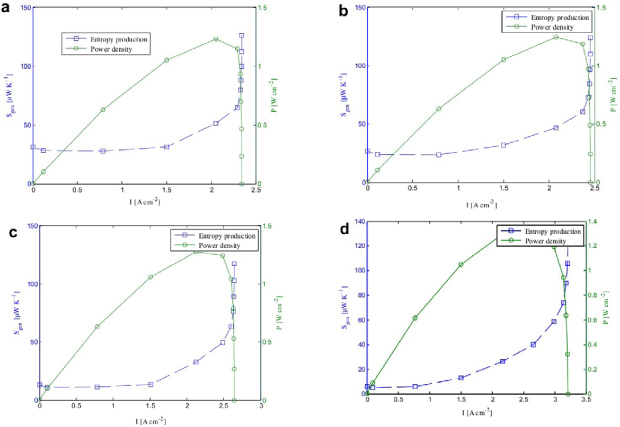
Figure 17. Power produced and entropy production for (a) very low; (b) low; (c) high; (d) very high humidity condition [22].
The importance of humidity in the fuel cell is with the transmission of the hydrogen ion needing the presence of water molecules to be able to transfer through the PEM to the cathode side [23]. Furthermore, from the research of the humidity in the system, the voltage output generated from varying the humidity variable is shown in the graphs below:
(Under the parameters of the rate of hydrogen and oxygen into the PEM is 0.5L/min, at the temperature of 55°C.) [23]
Which shows the factor of increasing the humidity produces a better voltage output compared to the ones with the lower humidity levels. In comparison to the two graphs, it was said by [23] that the increase in humidity at both ends increased the voltage output. However since the voltage output from the anodic side is much more vital for the fuel cell to operate, there needs to be a balance in the optimization of humidity to achieve the maximum output for the fuel cell [24].
The power output that can be generated from the anodic side from the variation of humidity can be shown in figure 20.
From figures 18-20 showing the improvement to the voltage output from the fuel cell, as Gholizadeh states in the conclusion to the study of humidity, ‘there is an optimized state both for humidity… and flow rate of humid gases that can provide the maximum performance of the fuel cell. [23]’ Which means if there is low or high water content in the membrane, then a reduction of the transference of hydrogen ion will lead to an underperformance from the fuel cell, therefore reducing the efficiency of the voltage generation [23].
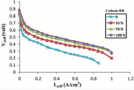
Figure 18. Effects of gas humidity variation in the cathode side [23]
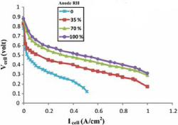
Figure 19. Effects of anode-side gas humidity variation [23]
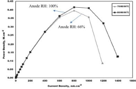
Figure 20. Effect of anode gas relative humidity (66% and 100%) on the cell power density at 80°C [24].
4. Conclusions
Entropy released as heat cannot be completely eliminated from the fuel cell technology because of the resistance from the membrane and the chemical reactions that produce the voltage needed. Not so much for the PEMFC, but since SOFCs run at high temperatures it is vital for these temperatures to be present. For air-breathing PEM fuel cell with Nafion membrane, there is optimal ambient temperature. As air-breathing fuel cell is highly affected by surroundings environment, the cell operating temperature is also highly rely on ambient temperature. With neither higher nor lower temperature than optimal temperature, the fuel cell is not operated with the best performance. Also, generally, PEM fuel cell with Nafion membrane cannot be operated at high temperature due to its limited proton conductivity at high temperature. Therefore it can be said that operating PEM fuel cell with Nafion membrane at high temperature is next for further study which is needed.
Current density and membrane thickness determined the scaling of the reaction, current density was limited by the electron permeability of the material and the membrane thickness determined the volume of material for current to pass through. The larger the amount of current going through the PEM, either from Amps or size of the membrane, the higher the rate of reaction and loss from inefficiency. A balance must be had between current and acceptable loss. A balance between humidity and pressure is important to supply the system with hydrogen for ion fuelling.
Using these results, focus can be directed towards finding membrane materials with the greatest permeability, cathode materials with the greatest polarity and improving hydrogen availability to the system.
Acknowledgments
The authors would like to acknowledge the support of Jurgen Schulte, Liam Martin, Blake Regan and the Energy Science and Technology class (2017 Autumn) from University of Technology Sydney, for guiding and reviewing this paper.
References and notes
1. Horschig, T; Thran, D, 2017, Are decisions well supported for the energy transition? A review on modelling approaches for renewable energy policy evaluation, Energy, Sustainability and Society, Vol. 7, no. 5, pg. 1-15.
2. Al-Gwaiz, M; Chao, X; Wu, O.Q, 2017, Understanding How Generation Flexibility and Renewable Energy Affect Power Market Competition, Manufacturing & Service Operations Management, Vol. 19, no. 1, pg. 114-131. doi: https://doi.org/10.1287/msom.2016.0595
3. Brown, Theodore L; LeMay, H. Eugene Jr; Bursten, Bruce E; Murphy, Catherine J; Woodward. P, Langford. S, Sagatys. D, George. A, 2013, Chemistry: The Central Science, 3rd edition, Pearson, Australia.
4. Tsuchiya, H. (2004). Mass production cost of PEM fuel cell by learning curve. International Journal of Hydrogen Energy, 29(10), pp.985-990. doi: https://doi.org/10.1016/j.ijhydene.2003.10.011
5. Pavelka M, Maršík F. Detailed thermodynamic analysis of polymer electrolyte membrane fuel cell efficiency. Int J Hydrogen Energy 2013 6/10;38(17):7102-7113.
6. Ramousse J, Lottin O, Didierjean S, Maillet D. Heat sources in proton exchange membrane (PEM) fuel cells. J Power Sources 2009 7/15;192(2):435-441.
7. Alin C Fracas, Petru Dobra, 2014, Adaptive control of membrane conductivity of PEM fuel cell.
8. Zhang, X., Guo, J. and Chen, J. (2010). The parametric optimum analysis of a proton exchange membrane (PEM) fuel cell and its load matching. Energy, 35(12), p.5297. doi: https://doi.org/10.1016/j.energy.2010.07.034
9. Glavatskiy K, Pharoah JG, Kjelstrup S. Thermal phenomena associated with water transport across a fuel cell membrane: Soret and Dufour effects. J Membr Sci 2013 3/15;431:96-104. doi: https://doi.org/10.1016/j.memsci.2012.12.023
10. O'Hayre, R., Cha, S., Colella, W. and Prinz, F. (2016). Fuel Cell Fundamentals, 3rd Edition. 1st ed. John Wiley & Sons, p.68. doi: https://doi.org/10.1002/9781119191766
11. Naterer, G., Tokarz, C. and Avsec, J. (2006). Fuel cell entropy production with ohmic heating and diffusive polarization. International Journal of Heat and Mass Transfer, 49(15-16), pp.2673-2683. doi: https://doi.org/10.1016/j.ijheatmasstransfer.2006.01.009
12. Naterer, G.F.; Tokarz, C.D., 2006, Entropy Based Design of Fuel Cell, The American Society of Mechanical Engineers, Vol. 3, no. 2, 165-174. doi: https://doi.org/10.1115/1.2174065
13. Siemer, M; Marquardt, T; Huerta, G.V; Kabelac, S, 2017, Local Entropy Production Rates in a Polymer Electrolyte Membrane Fuel Cell, Journal of Non-Equilibrium Thermodynamics, Vol. 42, no. 1, pg. 1-30. doi: https://doi.org/10.1515/jnet-2016-0025
14. Jia Xing Liu, Hang Guo, Fang Ye, Chong Fang Ma. Two-Dimensional Analytical model of proton exchange membrane in the fuel cell. Journal of Energy volume 119 15 january 2017, pages 299-308.
15. Mert, S.O.; Dincer, I; Ozcelik, Z, 2012, Performance investigation of a transportation PEM fuel cell, International Journal of Hydrogen Energy, Vol. 37, no. 1, pg. 623-633. doi: https://doi.org/10.1016/j.ijhydene.2011.09.021
16. M.S. Ismail, , D.B. Ingham, K.J. Hughes, L. Ma, M. Pourkashanian, 2014, An efficient mathematical model for air-breathing PEM fuel cells, Applied Energy Vol. 135, pg.490-503. doi: https://doi.org/10.1016/j.apenergy.2014.08.113
17. Attluri R. Vijay Babu, Pantalingal Monoj Kumar, Gorantla Srinivasa Rao, 2016, Effect of Design and Operating Parameters on the Performance of Planar and Ducted Cathode Structures of an Air-Breathing PEM fuel cell, Arabian Journal for Science and Engineering, Vol.41, pg. 3415–3423. doi: https://doi.org/10.1007/s13369-015-1890-8
18. W. Li, C Shen, X. Zhang, G. Kong, C.Chen, 2016, Preparation of high-temperature proton exchange membrane based on aminopropyltriethoxysilane and amino trimethylene phosphonic acid.
19. Jianlu Zhang, Yanghua Tang, Chaojie Song, Juijun Zhang (2007) Polybensimidazole-membrane-based PEM fuel cell in the temperature ange of 120-200°C. Journal of Power Sources, Pages 163–171. doi: https://doi.org/10.1016/j.jpowsour.2007.07.047
20. Blunier, B. and Miraoui, A. (2007). Air management in PEM fuel cells: State-of-the-art and prospectives. 2007 International Aegean Conference on Electrical Machines and Power Electronics, p.4. doi: https://doi.org/10.1109/ACEMP.2007.4510510
21. Li, X. and Faghri, A. (2011). Local entropy generation analysis on passive high-concentration DMFCs (direct methanol fuel cell) with different cell structures. Energy, 36(1), p.410, 412. doi: https://doi.org/10.1016/j.energy.2010.10.024
22. Rangel-Hernandez, V., Damian-Ascencio, C., Juarez-Robles, D., Gallegos-Muñoz, A., Zaleta-Aguilar, A. and Plascencia-Mora, H. (2011). Entropy generation analysis of a proton exchange membrane fuel cell (PEMFC) with a fermat spiral as a flow distributor. Energy, 36(8), p.328. doi: https://doi.org/10.1016/j.energy.2011.05.031
23. Gholizadeh, M; Ghazikhani, M; Khazaee, I, 2017, Experimental study of humidity changes on the performance of an elliptical single four-channel PEM fuel cell, Heat Mass Transfer, Vol. 53, no. 1, pg. 233-239.
24. Ozen, D.N; Timurkutluk, B; Altinisik, K, 2016, Effects of operation temperature and reactant humidity levels on performance of PEM fuel cells, Renewable and Sustainable Energy Reviews, Vol. 59, pg. 1298-1306. doi: https://doi.org/10.1016/j.rser.2016.01.040