Integrated Gasification Combined Cycle from coal
1. Jacky Chou, E-Mail: Jacky.Chou@student.uts.edu.au
2. Kieran Giouzelis, E-Mail: Kieran.Giouzelis@student.uts.edu.au
3. Jeremy Yeung, E-Mail: Jeremy.Yeung@student.uts.edu.au
* Author to whom correspondence should be addressed; E-Mail: Jeremy.Yeung@student.uts.edu.au
DOI: http://dx.doi.org/10.5130/pamr.v3i0.1418
Abstract
An integrated gasification combined cycle (IGCC) is a technology that uses a high pressure gasifier to turn coal, a carbon based fuels into pressurized gas, this is also known as synthesis gas or syngas. The IGCC system consist of 4 main structures; air compression and separation unit, gasifier, combustion and steam turbine and heat recovery generator.
A meta-analysis was conducted to investigate possible relationships between the efficiency and types of gasifiers used in the integrated gasification combined cycle in terms of the key thermodynamic laws. Through this analysis correlations were established between varying coal compositions, types of gasification systems and thermal efficiency. It was found that the updraft gasifier had the highest efficiency across most reports, thus making this procedure the most efficient with today’s current knowledge in terms of the thermodynamic principles associated with coal-fired power plants. It was also established that coal with lower moisture content will generally allow a system to be more efficient.
Keywords: Integrated gasification combined cycle (IGCC), Syngas, thermodynamics, efficiency
1. Introduction
The integrated gasification combined cycle process is one of the newest, most innovative coal-based power plant systems in today’s society. This is why we, as scientists, have chosen to perform a meta-study based on systems associated with the IGCC process due to its clean-burning, synthetic gas (syngas), which is stripped of pollutants and impurities and burnt to produce power yielding a much higher efficiency than any of its predecessors.
Through this meta-study the analysis of efficiency for the integrated gasification combined cycle (IGCC) power plants will be investigated across many fields of similarities, between the chosen fields the common factor is efficiency in which it’s the ratio of the amount of useful work done and the amount of final energy that it achieved. The to be investigated fields range from; the types of coal, the development in IGCC, Law of thermodynamics, efficiency in type of coal and gasifier and finally the type of gasifiers. Through using different types of coals that can be founded the process within the IGCC power plant differs in ways of preparing the coal feedstock for the gasifiers to produce energy, this allows for a differences and similarities in the efficiency across the above fields. Furthermore, evaluating and interpreting scientific articles and journals, a general idea is formed upon what is required to achieve the title of the most efficient technique to produce power from an IGCC power plant.
1.1. Types of Coals
Coal is fuel obtained from dead organic matter. It is primarily made up of 65-95% carbon and other constituent include hydrogen, sulfur, oxygen and nitrogen. Coal is an abundant resource, representing 41% of the world’s electricity needs. There are four types of coal that have different properties usually depending on their ages and the depth they were buried. These coals are lignite, subbituminous, bituminous and anthracite with respect to the amount of energy provided. As the organic matter is buried with pressure, heat and time the coals becomes less moist, hence lower degree of oxidation to achieve because of the energy needed to vaporize the moisture and liquefy the ash.
1.2. The Process of IGCC
Figure 1 shows the main structure of a coal based IGCC plant. The coal is supplied to the gasifier where it is partially oxidized under pressure, converting the coal and oxygen into synthesis gas, as well as producing steam. The plant uses oxygen as oxidant and therefore has an air separation unit (ASU). The hot syngas is processed to remove sulfur and other impurities compounds. At this point, CO2 may also be captured. Because of the high partial pressures of the species and the low volume flow of syngas, the gas cleanup process is very efficient and low cost compared to traditional flue gas cleaning.
The clean syngas is then fed to a combustion turbine for the production of electricity. The combustion turbine may also integrate in two different ways with the ASU. The heat in the exhaust gasses from the combustion turbine is recovered in the heat recovery steam generator (HRSG) to generate additional steam. The steam then drives a steam turbine generator to produce additional electricity.

Figure 1. Process of IGCC [1]
2. Method
A meta-analysis was conducted across a large range of reports involving four IGCC systems. Correlations and ideas that were common across this range of reports were found involving varying coal compositions, types of gasification systems and thermal efficiency of these systems and used to create connections across literature. Due to the limited information that directly correlated to these preceding categories, articles published within the last 15 years of this study were referenced. The data was collected using the information provided by the aforementioned parameters using scientific databases including SCOPUS, Google scholar, Access Science and various other internet websites. This was done to ensure that only the most recent and authentic findings were explored throughout this study.
3. Results and Discussion
3.1 Efficiency
Efficiency is a broadened term to define the ratio in which the work is done and the amount of energy that is obtained. Efficiency defined through the meta-study can be described into two categories in which they are the composition of coal and types of gasifiers. The two mentioned categories are both key factors that contribute towards efficiency in the integrated gasification combined cycle (IGCC) power plants. An IGCC power plant can have a plant efficiency of greater than 43% depending on the gasification. Through an in depth analysis for both the composition of coals and gasifiers in respect to efficiency, advancements can be made to allow for a better efficiency.
3.1.1 Efficiency of the coal composition
Five different coals as described in figure 2 were used in the calculation of thermal efficiency correlating with Figure 3. These coals range in rank from lignite (Coal 5) to low volatile bituminous (Coal 1) and differ significantly in moisture, ash content and heating values. These differences in the above factors display significant variations in efficiency levels.
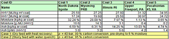
Figure 2. Types of Coals Used [2]
The differences are summarized in Figure 3. As shown in Figure 3, the efficiency in Case 2 in relation to the types of coal has a much larger impact than in Case 1. The observed drop in efficiency for lower rank coals is due to the amount of moisture of the coal which is represented in Figure 2. The moisture content varies with coal type and more strongly with particle size fineness; as the coal is ground more finely, more water is needed to maintain sufficiently low viscosity for trouble free slurry transportation [3].
In a dry coal feed gasifier, it is far more efficient to use a low rank high moisture coal as shown in Figure 3. However, high moisture coals are required to be pre dried in preparation for lock hoppering and pneumatic conveying [3]. This leads to a loss in energy as the presence of steam drying reduces the steam turbine output.

Figure 3. The Thermal efficiency in relation to Figure 1.
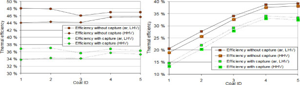
Figure 4a. Efficiencies for Case 1 – IGCC with dry feed gasifier and heat recovery (Left). [2]
Figure 4b. Efficiencies for Case 2 – IGCC with slurry feed gasifier and water quench. (Right). [2]
As shown in Figure 4a and 4b, Case 1 is less sensitive to the type of coal used due to less vibrations present in the energy density of the coal feed in respect to the gasifier [2]. When comparing the efficiency for Coal 1 and Coal 5 for Case 1, the lower heating value (LHV) efficiency for the lowest rank coal is higher than the highest rank coal. This result is unexpected, as the efficiency of the higher heating value (HHV) gives the expected result that the efficiency of Coal 5 is higher than for Coal 1 for reasons stated earlier in this paper. This can be explained due to having a LHV. It should be noted that LHV excludes the energy required to vaporize the water from the coal [2].
The efficiency is also dependent on the amount of CO2 emission [2]. Using an example from Figure 3, Coal 1 without CO2 has a higher efficiency than with CO2, this is because operating at a lower efficiency means that a relatively large amount of coal must be used to produce each unit of electricity [4].
There are many factors that will influence the efficiency. This includes coal types and gasification technology. In relation to coal types, high rank coals can be gasified more efficiently than coals from low rank [4]. This is due to the fact that higher moisture and ash content of low rank coals require a higher degree of oxidation to achieve slagging temperature because of the energy needed to vaporize the moisture and melt the ash. The other factor, being gasification technology, relates to how gasifiers with a dry feed are more efficient than gasifiers with a slurry feed because less water is vaporized [4].
3.3 Types of gasification systems
Through this meta-study a greater understanding has been constructed towards the thermodynamics behind the process of gasification. Gasification is the process of using coal a carbon based fuel and converting it into a gas in which it can be used for combustion to power the turbines, the gas can also be called as synthesis gas (syngas). Furthermore, in this meta-study, four main gasifiers will be looked upon in greater detail. It should also be noted that when performing any energy transfer, some amount of energy is inevitably lost, usually in the form of unusable heat energy, therefore no energy transfer is ever 100% efficient. In saying this though, the less unusable energy that is lost from a system, the more ordered and less random the system is. This means that in order to establish which of the four systems is significantly better than the rest, the system with the least entropy needs to be established.
3.3.1 Updraft gasifier
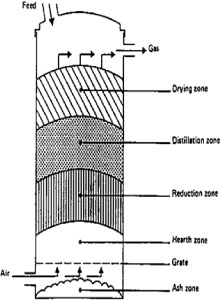
Figure 5. Structure of an updraft gasifier. [5]
An updraft gasifier is the fundamental gasifier as it’s to be considered one of the oldest and most simplistic gasifier that has been used. The favorable characteristic of the gasifier is shown through the simplicity of operation in which it allows equipment’s to produce average efficiency at moderate levels of oxidants and produce gas at a relatively low temperature, in which high temperature heat recovery generators are not needed. Updraft gasifiers produced energy through the addition of the feedstock in the form of large coal particles, larger coal particles are used to provide a greater permeability and the bypass of the drop of pressure and chemical burning.
Different types of reactions occur in different sections of the gasifier, within the upper half of the vessel, the entering coal is dried and heated, whereas the synthesized gas is being cooled before leaving the reactor, this zone is called the drying zone. The coal then enters the distillation zone in which it’s heated further as it descends through the gasifier. In the reduction zone the coal is gasified through reacting it with steam and carbon dioxide, upon reaching the bottom of the gasifier the combustion zone operates at the high temperature of approximately 1000°C, the remaining feedstock reacts with the oxygen in which it produces ash.
The process burning the feedstock to produce the syngas which allows for the production of energy shows pros and cons towards the efficiency, the ability to evenly burn the provided feedstock allows for a greater amount of syngas being produced and therefore more can be used to generate the system. Similarly, this also displays the cons of the system as upon burning all the feedstock the produced syngas has to travel back up towards the top of the gasifier and during this phase contamination of the syngas may occur, in which it hinders the efficiency [6]. In the long run this tiny drawback can lead to a significant difference between systems as the extensive loss of energy will show a drop in the overall efficiency of updraft gasifiers.
3.3.2 Downdraft gasifier
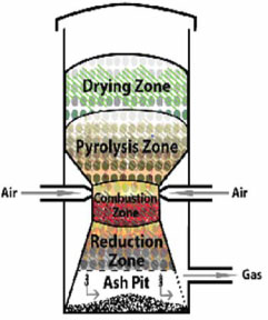
Figure 6. Structure of a downdraft gasifier. [5]
A downdraft gasifier or co-current gasifier follows a similar design to an updraft gasifier, in which they both consist of a drying zone, distillation zone, reduction zone and combustion zone. The downdraft gasifier also provides a solution towards tar contamination found in the upward draft gasifier, this is done through removing the synthesized gas at the bottom of the gasifier and allowing the fuel and gas to travel in the same direction.
The downdraft gasifiers display an advantage that allows for the production of tar free syngas which can be used in engine operation, even though tar free syngas isn’t commonly used the less tar content in the product is still considerably lower than the updraft gasifier. The disadvantage of the downdraft gasifier is the inability to operate with a variety of feedstock, this is limited to high density feed stock as low density feedstock will lead to an excessive pressure drops and a rise in flow problems, another limitation is having higher ash content coals will also have led to other issues. Efficiency of the gasifier is also very limited as there is no internal exchange in comparison to the updraft gasifier, the lowered efficiency directly affects the calorific values in the final production. Furthermore, downdraft gasifier shows similarities to the updraft gasifier but displays poorer functionalities with the same given feedstock. Both simplicity in operation and efficiency of the gasifier isn’t favorable with the downdraft gasifier.
The process of producing syngas in a downdraft gasifier is similar to some updraft gasifiers in which the burning the feedstock allows for the production syngas, but for a downdraft gasifier it displays aspects that are more positive than the updraft gasifiers. The ability to evenly burn the feedstock allows for the greater amount of syngas that can be used to generate the system, whilst in the updraft gasifier the syngas has to travel towards the top of the gasifier to be cooled in preparation for using, the downdraft gasifier extracts the hot syngas (900°C to 1000°C) at the bottom which can limit the amount of contamination that can occur and thus leading to a much more pure and efficient syngas. Furthermore, the extraction of the hot syngas allows for a reversed generation of power as it travels through a heat generator and thus providing another source of energy for the system [6].
3.3.3 Crossdraft gasifier
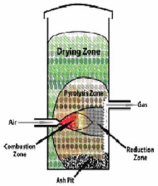
Figure 7. Structure of a Crossdraft gasifier. [5]
Similar to the updraft gasifier the Crossdraft gasifier is considered to be one of the simplest gasifiers, it follows the simple structure and method of operation. Even though common similarities are present in both gasifier, there are key points that distinguish them apart.
Crossdraft gasifiers display positive advantages over updraft and downdraft gasifiers, the ability to produce a much purer syngas is favorable as it allows for a greater combustion value, in which lead to a higher energy value ratio. Although producing purer syngas, Crossdraft gasifiers also display disadvantages in which it produces relatively higher exiting gas temperatures as the gas is not cooled due to gas exiting in the lower half, it also has a relatively poor carbon dioxide reduction and as well as higher gas velocity. All these limiting drawbacks of the Crossdraft gasifier is due to overall design of the gasifier. Furthermore, Crossdraft gasifiers display limiting drawbacks such as only being viable in developing countries, producing relatively high temperature while in combustion and loss of energy through producing charcoal from wood, therefore Crossdraft gasifiers are considered non favorable.
The production of syngas in a Crossdraft gasifiers follows a simple process but differs from the updraft and downdraft gasifier in which the feedstocks travels in a downward motion. Feedstock in a Crossdraft gasifier enters the system and wraps around the hot combustion zone where it is dried and prepared for combustion. Air enters from one side of the system during combustion of the feedstock whilst the produced syngas is extracted on the opposite side. This prevents contamination of the final product of the syngas as the syngas is unable to be in contact with the feedstock or the already burnt feedstock in the ash pit. Though the syngas isn’t contaminated by any impurities during the extraction, the exiting syngas is at high temperatures of 800°C to 1000°C which may hinder the performance of the overall system. Overall the Crossdraft gasifier displays lowered energy efficiency levels at the cost of less contaminated but purer syngas [6].
3.3.4 Fluidized bed gasifiers
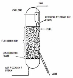
Figure 8. Structure of a fluidized bed gasifier. [5]
The processes of the previously mentioned gasifiers (being both the up and downward draft gasifiers) encounter several problems including lack of bunker flow, slagging and extreme pressure drops within the gasifier due to the fact that they are directly influenced by physical, chemical and morphological properties pertaining to the fuels used. The fluidized bed gasifier addresses these flaws.
Initially, air is blown through an externally heated bed of solid particles allowing them to remain in a state of suspension. The fuel particles then interact with the bed material and are almost instantaneously heated to the same temperature. The effects of this process create a component mix between the bed and fuel with is largely made of up gaseous materials. During this phase, further gasification occurs along with tar conversion as ash particles are carried over the reactor to be removed from the gas stream (this is done only for use in engine applications). This removal is done through the use of cyclone and candle filters are used. The main advantage of using this process is the processing of feedstock. This is why it is mostly used for high ash, coal and biomass as the temperature is always below the ash softening temperature, meaning that the handling of the ash is easiest in the process. A major drawback in relation to the fluidized bed gasifier is the high tar content present in the syngas produced along with incomplete carbon conversion why may hinder the efficiency of the syngas. The fluidized bed gasifier also functions at a lowered temperature in comparison to updraft, downdraft and cross draft gasifiers, where the optimal temperature of the fluidized bed gasifier is around 700°C to 900°C.
Furthermore, fluidized bed gasifiers display favorable characteristics such as being more packed and allows for an increased throughput level in comparison to fixed bed gasifiers such as the updraft and downdraft gasifiers. Fluidized bed gasifiers also contain pros and cons in terms of how efficient the system can be, where the system can produce low tar content syngas with increased levels of particulates, but the produced syngas provides lowered efficiency levels but can be improved upon recycling the gas back into the system [6].
4. Conclusions
Integrated Gasification Combined Cycle systems used in industry for the formation and production of syngas undoubtedly vary in regards to design and operation of the facility. By conducting this study, an analysis of the thermodynamic parameters of four systems was done; updraft gasifier, downdraft gasifier, cross draft gasifier and the fluidized bed gasifier and the quality of syngas from each system was found to be dependent upon several parameters including varying coal compositions, types of gasification systems and thermal efficiency. In saying this, a decrease in the moisture content of coal generally showed an increase in the thermal efficiency of a system. This study emphasized on the multifaceted relationship between each gasification system, in terms of the parameters associated in determining the quality of the syngas produced. Our group then concluded that the updraft gasifier had the highest efficiency across most reports, thus making this procedure the most efficient with today’s current knowledge in terms of the thermodynamic principles associated with coal-fired power plants. This was because of its capabilities involving its ability to change the temperature of the system freely, in comparison to the fluidized and downdraft systems.
Acknowledgments
Through completing this meta-study, the group would like the acknowledge Jurgen Schulte for assisting and providing guidance in this study.
References and Notes
1. “How IGCC Works”. Duke Energy. https://www.duke-energy.com/about-us/how-igcc-works.asp, 2016. Web. Accessed 20 May 2016.
2. Maurstad, Ola et al. “Impact Of Coal Quality And Gasifier Technology On IGCC Performance”. The Norwegian University of Science and Technology N-7491 (2016): pp. 2-6.
3. Beér, János M. “High Efficiency Electric Power Generation: The Environmental Role”. Progress in Energy and Combustion Science 33.2 (2007): pp. 107-134. doi: http://dx.doi.org/10.1016/j.pecs.2006.08.002
4. Maurstad, Ola. “An Overview Of Coal Based Integrated Gasification Combined Cycle (IGCC) Technology”. Laboratory for Energy and the Environment LFEE 2005-002 WP (2005): n. pp. 2-11
5. “Types Of Gasifier – Enggcyclopedia”. Enggcyclopedia.com. http://www.enggcyclopedia.com/2012/01/types-gasifier/, 2016. Web. Accessed 20 May 2016.
6. Roos, Carolyn J. “Clean Heat And Power Using Biomass Gasification For Industrial And Agricultural Projects”. WSU Extension Energy Program (2010): pp. 9-15.
7. “2.3 Types Of Gasifiers”. Fao.org. http://www.fao.org/docrep/t0512e/t0512e0a.htm, 2016. Accessed 20 May 2016.
8. “Clean Power”. Netl.doe.gov. http://www.netl.doe.gov/research/coal/energy-systems/gasification/gasifipedia/clean-power, 2016. Accessed 20 May 2016.
9. “Cross Draft Gasification Biofuels Academy”. Biofuelsacademy.org, 2016. Web .Accessed 20 May 2016.
10. “Cross-Draft Gasifiers”. Energy.kth.se. http://www.energy.kth.se/compedu/webcompedu/S4_Combustion/B10_Thermochemical_Conversion/_C1_Introduction_to_Gasification/ID55_files/Cross_Draft_Gasifiers.htm, 2016. Web. Accessed 20 May 2016.
11. Esmaili, Ehsan, Ehsan Mostafavi, and Nader Mahinpey. “Economic Assessment Of Integrated Coal Gasification Combined Cycle With Sorbent CO2 Capture”. Applied Energy 169 (2016): pp. 341-352. doi: http://dx.doi.org/10.1016/j.apenergy.2016.02.035
12. Giuffrida, Antonio et al. “Lignite-Fired Air-Blown IGCC Systems With Pre-Combustion Co2 capture”. International Journal of Energy Research 40.6 (2016): pp. 831-845. doi: http://dx.doi.org/10.1002/er.3488
13. Harris, David and Daniel Roberts. “Black Coal IGCC”. ANLECR&D Scoping Study EP103810 (2010): n. Pp. 3-43.
14. “How Is Coal Formed?”. Coaleducation.org. http://www.coaleducation.org/q&a/how_coal_formed.htm, 2016. Web. 20 May 2016.
15. McKendry, Peter. “Energy Production From Biomass (Part 3): Gasification Technologies”. Bioresource Technology 83.1 (2002): pp. 55-63. doi: http://dx.doi.org/10.1016/S0960-8524(01)00118-3, http://dx.doi.org/10.1016/S0960-8524(01)00119-5 and http://dx.doi.org/10.1016/S0960-8524(01)00120-1
16. “Second Law Of Thermodynamics”. Grc.nasa.gov. https://www.grc.nasa.gov/www/k-12/airplane/thermo2.html, 2016. Web. Accessed 20 May 2016.
17. “The Three Laws Of Thermodynamics”. Boundless (2016): https://www.boundless.com/chemistry/textbooks/boundless-chemistry-textbook/thermodynamics-17/the-laws-of-thermodynamics-123/the-three-laws-of-thermodynamics-496-3601/, Web. Accessed 20 May 2016.
![]()
©2016 by the authors. This article is distributed under the terms and conditions of the Creative Commons Attribution 4.0 International License (http://creativecommons.org/licenses/by/4.0/).