Determining the best approach to commercial fusion power
Karl Zuvela1,*, Isabella Adlington2 and Syed Salim Aljunied3, Jackson Edwards4
1 University of Technology, Sydney, PAM; E-Mail: karl.zuvela@student.uts.edu.au
2 University of Technology, Sydney, PAM; E-Mail: isabella.adlington@student.uts.edu.au
3 University of Technology, Sydney, PAM; E-Mail: syedsalim.aljunied@student.uts.edu.au
4 University of Technology, Sydney, PAM; E-Mail: jackson.edwards@student.uts.edu.au
* Author to whom correspondence should be addressed; E-Mail: karl.zuvela@student.uts.edu.au
Received: 4 April 2014 / Accepted: 28 April 2014 / Published: 2 June 2014
Abstract: This study sets out to determine which fusion power generator design is most suitable for centralised power production to be used commercially in communities comprising of domestic, corporate and industrial entities. We find there are currently only three main contenders in this field, those being the tokamak, the stellarator and the indirect-drive. Of these it is found that indirect-drive is too inefficient in comparison, though this is against theoretical numbers as the other systems are still under construction. We still are able to conclude that the stellarator is most likely to become the commercial power source.
Keywords: fusion; energy; tokamak; stellarator; indirect-drive; magnetic confinement; efficiency.
Copyright: © 2014 by the authors. This article is distributed under the terms and conditions of the Creative Commons Attribution license (https://creativecommons.org/licenses/by/4.0/).
DOI: http://dx.doi.org/10.5130/pamr.v1i0.1383
1. Introduction
Fusion works. It is the phenomenal heat produced in every proto- and mid-life star. To harness this heat before its dissipation through space the fusion reaction must be produced on Earth. That is the aim of a fusion power station, to produce the highest amount of useful output energy possible from the fuel, that is,

where η is the thermodynamic efficiency. In a nuclear fusion reaction Ein would partly be comprised of the heat of the fusion reaction and the provided externally to heat the plasma to ignition.
Energy density of Deuterium-tritium (D-T) fusion is approximately 3.4x10¹⁴ J/kg in comparison to 2.1x10¹² J/kg in uranium-235 (235U) fission; this is calculated using the difference in binding energies between reactants and products [1]. This energy cannot be completely harnessed, even in principle, due to the first law of thermodynamics. The specific energy density of fusion is several orders of magnitude more than chemical and renewable energy production such as coal burning and wind harnessing, respectively. A more in depth comparison with competing systems will be made in this study.
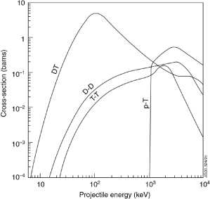
Figure 1. Nuclear fusion reaction cross-sections [2] involving hydrogen and isotopes of hydrogen.
It is common knowledge that the fuel for first generation fusion stations will be D-T, producing Helium-4 and a fast neutron (approximately 17.571x10³ eV). These neutrons are used in a feedback loop as they bombard a lithium barrier to produce Tritium for the next fuel injection. There are three more possible reactions that are considered for fusion, these being D-D, T-T, and p-T (proton-tritium). The D-T reaction is chosen over these others due to the reaction cross-section (probability of a fusion reaction) being almost two orders of magnitude higher and at lower temperature, as seen in Figure 1.
It can be seen from the Lawson criterion [3] that the larger the cross-section the larger the power released,

where n1 and n2 are the densities of nuclei, 〈νσ〉 is the product of the relative velocities of nuclei with the nuclear reaction cross-section averaged using the Maxwellian distribution, and E is the energy released in one reaction. This energy is collected as it heats the working medium liquid lithium blanket or helium gas [4], which may then be cooled by water. ITER, currently under construction, will be testing a Helium Coolant Lithium-Lead blanket to both conduct heat and breed tritium.
Looking at power production the fusion energy gain factor [5], or the Q factor, becomes important. This describes the ratio of fusion power produced to the power required to heat the plasma in a steady state. The equation that describes this ratio is

Here Pfus is the fusion power density, Pheat is the external power for heating the plasma, ηheat equals the conversion efficiency of external power to Pheat, frecirc is the fraction of power recirculated from the fusion reaction to power the reaction, ηelect is the efficiency of the working medium converting heat to electricity, and fc equals the fraction of power from charged products in the plasma. A Q factor of 1 is where the input power equals the output power and has become known as break even. The Q factor will be a part of the analysis of results in this study.
Second and third generation fusion reactors are hypothesised to employ deuterium and helium-3 (D-3He), and 3He-3He, respectively. Both of these reactions produce an energetic proton that can interact with an electric or magnetic field directly producing electricity. The benefit of 3He-3He is no production of fast neutrons, however much higher temperatures are required for the nuclei to have a high probability for tunnelling through the larger coulomb barrier and the proposed collection of 3He leans more to science-fiction than current technology allows. One suggestion is mining the Moon [6], while another popular suggestion in science-fiction writing is constructing cloud scoops on Jupiter. These possibilities would be far into humanity’s future if they are to come to fruition.
1.1. Tokamaks and Stellarators
As the particles in D-T fusion are charged they can be influenced by an external magnetic field. Using a magnetic field allows for the plasma to be confined to fusion temperatures without spreading out. To confine the plasma a helical magnetic field must be used as other magnetic field shapes allow for the plasma to pass through gaps when the containment chamber is expanded with heat.
The most researched approach to magnetic confinement is the tokomak and is the method to be used in the international thermonuclear experimental reactor (ITER). It uses two magnetic fields, the toroidal field and a poloidal field to confine the plasma.
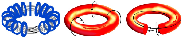
Figure 2. Tokamak magnetic field shapes. Left: toroidal magnetic field (arrows) generated from the coils (blue), middle: transient poloidal field (black arrows) due to plasma current (red arrow), right: resultant helical field from the two primary fields
The design of a tokomak has basically two magnetic fields as shown in the diagram below. The toroidal field coils are wrapped around the structure giving it a torus shaped magnetic field, the poloidal field coils are placed on the outside of the toroidal coils creating magnetic fields that loop around the torus and induce current to drive the plasma, in the ITER a central magnetic solenoid is used as the primary plasma driver with the poloidal field adding to it. The magnetic fields are shown in the images.
This field shape allows for the plasma to be completely encompassed allowing for proper confinement. Though the instabilities in the plasma only allow for reactions to happen for a very short time. Another problem that the tokomak faces is the blanket on the inside of the reaction vessel. Because the plasma is around the temperatures of 1x10⁸ K a material must be chosen that has a very high melting point and has a low vapour pressure to eliminate the risk of contaminating the plasma, for this reason the ITER uses beryllium.
Tokamaks use four types of methods to heat the plasma, these methods are ohmic heating, neutral beam injection, magnetic compression and radio frequency heating. Ohmic heating exploits the fact that the plasma generated is an electrical conductor as a current is induced in the plasma its temperature will increase. Neutral beam injection consists of deuterium particles being accelerated and passed through a ion beam neutralizer to remove the electrical charge from this they are injected into the plasma where collisions transfer the energy of these particles to the plasma. Magnetic compression works by rapidly compressing the plasma which in turn increases the temperature. Radio frequency heating uses electromagnetic waves produced outside of the torus by an oscillator, if the waves are of the correct frequency then they will transfer heat to the system. All of these techniques are used in the ITER to produce temperatures on the order of 1x10⁸ K.
The other device that uses magnetic confinement is a stellarator, while there are quite a few feature that both devices share the stellarator is distinct in the fact that it is not azimuthally symmetric. The shape of the device is shown below.

Figure 3. Example shape of a stellarator.
Because of this shape it is much harder to manufacture parts for the stellarator and the magnetic field is weakened as well. The upside is that stellarators do not require a toroidal current. The most recent stellarator is the Wendelstein 7-X which is being built at the Max Planck institute and will be completed by 2015 [7].
As the ITER is expected to be completed by 2019 [8] the Wendelstein will be able to show what the stellarator design is able to do. With the completion of both of these reactors we might be able to see if magnetic confinement fusion is a viable method (produces more energy than other commercial sources) for sustainable energy.
1.2. Indirect-Drive
This method does not rely on the force of a magnetic field to confine the fuel but by the inertia of the fuel mass itself. This process starts with a capsule filled with the frozen or liquid D-T mixture, Energy from a driver is delivered rapidly to the outside surface (ablator) of the capsule which causes expansion of the ablator. As the ablator expands the inside shell must compress to conserve momentum. As this decrease in volume of the fuel increases the temperature in the centre of the capsule to fusion conditions, ions start to fuse from the centre and move outward into the main amount of fuel. This process only takes 10-11 to 10-9 second [9] to happen the ions do not move due to their own inertia still pushing them to the centre. There are two main techniques on how this is achieved, one is by direct drive where the laser is aimed directly at the target whereas the other technique indirect-drive the energy from the laser is absorbed by a hohlraum and converts it into x-rays which drive the implosion. There will be more focus on indirect-drive as this is the method that the national ignition facility uses to obtain fusion.
National ignition facility creates one weak laser pulse which is then split and carried by optical fibre to 48 preamplifiers that increase the energy by a factor of 1010. The beams are then split in four and passed to the 192 main laser amplifier beam lines. Each beam is passed through a power amplifier followed by the main amplifier which traps the light by an optical switch so that the beam is of high quality. From there it passes through the power amplifier again so that the total energy of the beams is 4 MJ [9]. The beams are split in the switchyard to groups of four creating a 2x2 array and pass through the final optics assembly where the beams are converted from the infra-red to ultra-violet spectrum. They are then focused on the hohlraum capsule, as the beams strike the inside of the wall of the capsule x-rays are created which compress the fuel to fusion conditions.
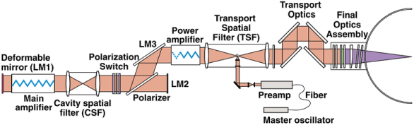
Figure 4: NIF beam path (http://en.wikipedia.org/wiki/File:NIF_beamline_diagram.png).
The national ignition facility could get close to the break even threshold by 2014 but for a fusion reactor to be economic it will need to produce 50 times more energy out of the system than into the system to be an effective energy source. This would mean it would need shot rate (number of pellets fused or known as a shot) to be about 15 per second [10]. Though in 2013-2014 there are still problems with this technique such as the fuel is resisting compression and not absorbing as much of lasers energy as it needs to. Though the facility has reached the milestone of reactions producing more energy than the fuel absorbed but it is still nowhere near the amount to break even the two shots with output energies of 14.4 and 17.7 kJ compared to the energy deposited into the fuel of 11 and 9 kJ respectfully [11]. This inefficiency of the Device is that the hohlraum is very inefficient in converting the energy of the laser into x-rays, the figure was about 25% when the energy of the laser was at 1.8 MJ [12]. This shows that there is a long way to go for indirect-drive fusion in terms of fusion gain. There also has to considerations that the amplification process of laser does not have great efficiency as in 2014 the best shot at NIF had an overall gain of only 0.01 [11]. Using the direct drive approach where the fuel pellet is targeted directly instead of using a hohlraum. This could make the process more efficient but require the use of an ablator as well as there is less development in the field currently (NIF and LMJ both use the indirect approach).
2. Methodology
This study will be limited to the research of first generation fusion power and attempting to infer which will be best suited as a centralised commercial source of energy production and attempt to determine whether decentralising power with smaller units may be a feasible option. Feasibility of smaller units will be determined on the efficiency of the fusion techniques at much smaller volumes.
Fusion reactor designs chosen for review were the Tokamak, Stellarator, and indirect-drive. These were chosen from a large array of designs, most of which were discarded for review due to the lack of research. Information was gathered from numerous databases provided by the UTS library with articles limited to no older than 15 years for with focus on newer papers for results on current reactors. This also allowed us to gain insight to how the technologies have progressed within this time period. Background information for confinement methods was gathered from websites and other online sources of information.
3. Results and Discussion
Most of the values in the results tables are theoretical, and have not been achieved experimentally. The exception to this is the data from the National Ignition Facility, where the working fusion reactor recently achieved ‘unity’.
The data, although mostly conceptual, is promising and worth researching for further development. Tokomaks, stellarators and indirect-drive are all viable methods of eventually achieving sustainable nuclear fusion reactions that could be used commercially, that is, produced in a power plant and used to provide energy to society, for example, a community comprising of domestic, corporate and industrial entities.
One of the most crucial elements in harnessing fusion energy is effective heat transfer [16]. Tokamaks use diverters, a cooling blanket to transfer heat to water to create steam for electrical energy. Cooling blankets, however, are susceptible to damage from infiltration of neutrons, very high temperatures, and chemical erosion (from ionisation from the plasma), so a very large obstacle to overcome is the material/s to use in the blanket. If the blanket is damaged, the system can lose confinement, and the reaction will not take place. The goal is to find a material that is thermodynamically efficient and will not be susceptible to damage given the conditions of confinement.
| Parameter | ITER | ARIES | Demo A | Demo AB | Demo B | Demo C | Demo D |
| Gross Electrical power (GWe) | - | - | 2.066 | 2.385 | 2.157 | 1.696 | 1.640 |
| Net Electrical power (GWe) | - | 1 | 1.546 | 1.5 | 1.332 | 1.449 | 1.527 |
| Fusion power (GW) | 0.5 | 1.7 | 5 | 4.29 | 3.6 | 3.41 | 2.53 |
| Q | 10 | 47 | 20 | 16.5 | 13.5 | 30 | 35 |
| Plant efficiency (%) | – | 59 | 31a/33b | 35 | 36 | 42 | 60 |
| Major radius (m) | 6.2 | 5.2 | 9.55 | 9.56 | 8.6 | 7.5 | 6.1 |
| Neutron wall load (MW/m2) | 0.78 | 3.3 | 2.2 | 1.8 | 2 | 2.2 | 2.4 |
| Heat load first wall (MW/m2) | 0.5 | 0.45 | 0.6 | 0.5 | 0.5 | 0.45 | 0.5 |
| Diverter peak load (MW/m2) | <10 | 5 | 15 | 10 | 10 | 5 | - |
Model A uses water to cool blanket at 15MPa and 300 °C, and Li-Pb (17mol% Li, 83mol% Pb) to produce tritium. The maximum electrical power output is 1.55 GWe, and the maximum efficiency is 31%. Model B uses He to cool blanket and diverter at 8MPa and 300-700 °C, and Li4SiO4 and Be for tritium production. Maximum electrical power output is 1.33 GWe, and efficiency is 37%. Model C uses dual coolant configuration (for thermal efficiency); He to cool blanket, Li-Pb for removing neutron generated heat. Li-Pb is circulated through SiC lined tubes to minimize MHD effects and for tritium production. The maximum electrical power output is 1.45 GWe, and the efficiency is 42%. Model D uses Li-Pb for cooling and tritium production. The maximum electrical power is 1.53 GWe, and efficiency equals 60%. ARIES is not a DEMO, it is an advanced model that aims to be able to produce energy for commercial use. It employs liquid metal Li-Pb at 1000 °C for the cooling blanket. Maximum electrical power is 1.00 GWe, and efficiency is 59%.
All power sources had similar outputs in electrical power, but reactors with more advanced cooling devices and heat transfer systems had higher efficiencies.
The National Ignition Facility have recently succeeded in achieving ‘unity’: where the ratio G is greater than one. [19] This is a significant improvement from all other experiments they have performed, and has only ever been a theoretical value (as seen in table 1).
In terms of cost and space, for each run of the national ignition facility uses only US$5 worth of electrical energy as input for each reaction, and they aim to reduce this to 50 cents. The overall cost of the facility, however, is quoted at US$3.5 billion [9].
The ITER project – a collaboration of 35 nations – has so far cost €13 billion, and will occupy a facility around 2.5 million m3 in size (including the reactor, research facility, etc.) [20].
| Parameter | NIF A | NIF B | NIF C | NIF D | NIF E |
| Input energy (kJ) | 8.5–9.4 | 10.2–12.0 | 10.0–13.9 | 10.92–11.19 | 13.4 |
| Fusion energy (kJ) | 17.3 | 14.4 | — | — | 25.1 |
| Q | 1.8–2.0 | 1.2–1.4 | 1.04–1.44 | 1.28–1.31 | 1.9 |
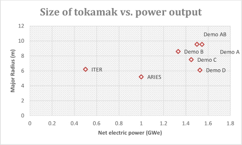
Graph 1. Relates to table 1 and depicts proposed tokomak size relative to their output power.
The question now would be, why use fusion? There are many competing energy systems currently being used. The fossil fuel sector is currently providing the world with roughly 75% of its energy needs; this includes coal, petroleum and natural gas. The remaining energy is provided by renewable energy such as solar, wind, hydro, biofuel, geothermal and finally nuclear.
Every system in use has their advantages and disadvantages and from these we will see whether Fusion is commercially viable. Between the different fusion methods, electrostatic inertial confinement, magnetic confinement and inertial confinement, it is magnetic confinement that seems to have the most promise.
Within Fusion, we are restricted by current technologies that make it non-viable commercially. At this stage, the ITER project is the most prominent fusion power project but it will not be commercially ready. ITER is a scientific stepping stone for fusion power, leading into the DEMO project and ultimately PROTO (commercial sized fusion power station).
The objective of ITER is not to produce a commercially ready fusion power plant but to look into resolving many issues in dealing with Plasma and technologies that enable Fusion to be functional. As with the result shown in above, Fusion has a long way to go as ITER’s focus to produce a Q value of 10 or greater briefly is still not commercially viable. The results also show that electricity production is not applicable, this is due to the experimental nature of ITER which is not designed to produce electricity.
| ITER | KSTAR | EAST | JET | SST1 | IR-T1 | JT-60 | |
| Toroidal field, Bθ(T) | 5.3 | >3.5 | 3.5 | 3.5 | 3 | 1 | 4 |
| Plasma current, IP (MA) | 15 | >2.0 | 1.0 | 5 | 220x10-3 | 40x10-3 | 3 |
| Major radius, R0 (m) | 6.2 | 1.8 | 1.85 | 2.96 | 1.1 | 0.45 | 3.4 |
| Minor radius, a (m) | 2.0 | 0.5 | 0.45 | 2.1 | 0.2 | 0.125 | 1 |
| Elongation, κ | 1.7 | 2 | 1.6 - 2 | 1.9 | 1.7-2 | 1.8 | |
| Triangularity, δ | 0.33 | 0.8 | 0.6 - 0.8 | 0.5 | 0.4-0.7 | 0.4 | |
| Plasma volume (m3) | 830 | 17.8 | 90 | ||||
| Plasma surface area (m2) | 680 | 56 | |||||
| Plasma cross section (m2) | 22 | 1.6 | |||||
| Pulse length (s) | 400 | >300 | 1-1000 | 60 | 1000 | 35x10-3 | 65x10-3 |
The table above is a compilation of some parameters from different Tokamaks currently in operation compared to ITER. These Tokamaks are part of the ITER project and focus on different research and engineering projects to contribute to the future of fusion energy. Most current projects are now trying to develop steady state operation of the Tokamaks. From table 3, we can see some parameters are missing. The missing information can be critical in solving different problems that can arise in future projects as the information can be used as a comparison of successful operation. As these projects are carried out with the same intent of creating a sustainable fusion source, a set of standard parameter measurement should be laid out to enable easier collaboration with different plants. A set standard will better communications within fusion research and can help accelerate its ready date. This ties in to the development of ITER and ultimately DEMO as these projects all have a common aim.
By following the timeline and current status of ITER, we can then project when usage of Fusion will be commercially viable.
| Date | Event | Status |
| 2006 | ITER project is formally agreed upon by participants | Completed |
| 2008 | Site levelling/preparation | Completed |
| 2013 | Tokamak complex construction starts | Completed |
| 2015 | Tokamak assembly starts | Planned |
| 2017 | Conceptual design for DEMO completed | Predicted |
| 2019 | Complete Tokamak assembly, commissioning begins | Planned |
| 2020 | First Plasma | Planned |
| 2024 | Engineering design for DEMO completed | Predicted |
| 2027 | Start Deuterium-Tritium Operations of ITER | Planned |
| 2030s | Construction of DEMO | Predicted |
| 2040s | First phase of DEMO operation | Predicted |
| 2040s onwards | Second phase of Demo/ PROTO | Predicted |
As shown above, Fusion will not be ready till 2050 [22, 23] but considering the status of the world’s consumption of energy, this is not necessarily negative. Looking at the “BP Statistical Review of World Energy 2013” [21], the trends of energy consumption can be picked out and estimated. This shows that by the time Fusion is ready after 2040 [22], most of the fossil fuels currently in use would have severely dropped in resources. Fusion’s estimated completion date for it to be commercially viable comes within a good timeframe to replace fossil fuel power.
3.1. Comparison to Other Energy Sources
3.1.1. Fossil Fuels
Producing roughly 80% of the world’s energy [24], fossil fuels are currently the main source of the worlds’ energy. This is due to the large abundance of fossil fuels available to the world and fuels being easily combustible. The process used is also much simpler to implement compared to other fuel sources. Resource for fossil fuels will be able to last well into the future and when fusion is ready for commercial activates but in the end, it is a finite source and will eventually run out even with increase in efficiencies and advances in technology regarding energy production in this area.
3.1.2. Coal
Coal is the easiest to mine out of the 3 fossil fuels making it the least expensive and the most readily available source. With its large reserves and ease of accessibility, it is easy to see why this is an option used widely around the world. The current demands of energy are easily met by Coal with the needs out-weighting the disadvantages of using Coal as an energy source.
| Energy Source | Thermal Efficency | Advantage | Disadvantage |
| Nuclear Fusion | 48% |
|
|
| Coal | 32%-42% (depending on pressures) |
|
|
| Natural Gas | 32%-38% |
|
|
| Oil | 35%-42% |
|
|
| Nuclear Fission | 33%-37% |
|
|
| Solar Power | 20% |
|
|
| Hydro Power | 80%-90% (no heat loss through thermo-dynamic or chemical process) |
|
|
| Geothermal | 10%-20% |
|
|
3.1.3. Oil
Oil has the highest power output compared to the other 2 fossil fuels allowing it to be the leading worlds’ fuel source, accounting for 33.1% of the worlds’ energy production. It is fairly easy to transport and distribute, has many applications and is more efficient compared to the other two fossil fuel. Oil also burns cleaner then coal.
3.1.4. Natural Gas
There are many advantages of using Natural Gas compared to the other fossil fuels, it burn much cleaner then both Coal and Oil, it can easily be transported through pipelines or tanks, can provided instant heating making it cheaper than using electricity and is relatively abundant.
Fossil fuels being a non-renewable energy source have a limited time usage, the Oil and Natural Gas reserves are estimated to last another 55 [21] years. Even thou Coal has a reserve to last a 100 years, the detrimental effects it has on the environment will cause it to be replaced as an energy source as soon as cleaner, more efficient and renewable sources are available. This puts the developments of Fusion in the right time frame to replace fossil fuels.
3.1.5. Renewable energy
Hydro, Solar, Wind, Biofuel, Geothermal and Nuclear Fission are the main renewable energy sources in the world. They provide a clean and promising future for energy production but have many disadvantages with current technologies. Hydro, Solar and Wind are essentially free energy that uses the natural environment around them and this poses their major problems. Hydro power although highly efficient, requires a large water source. Unless already available, creating a water source to support Hydro power can create a large environmental problem. Solar power currently do not have the technology to be highly efficient in production of energy, this creates a problem as a large scale of solar panels are needed to sufficiently generate power. Wind power does not have as large a footprint as Hydro or Solar but are the least efficient of the three, they also pose a danger to local flying wildlife.
Geothermal energy which taps the heat content of Earth’s core is considered renewable as the amount of heat extracted is small in comparison with Earth’s thermal content. Currently only a small percentage of energy produced is by geothermal. The main issues with geothermal are the initial start-up cost that can be very high, drilling down into the thermal wells can cause the land to be destabilised. Drawing fluids from the required depths also include the risk of carrying other mixtures of gases which can be potentially hazardous.
Nuclear fission is able to produce large amounts of power but leaves behind radioactive waste material which can take thousands of years to get rid of. This waste is also used in weaponry to create “dirty” bombs which are unethical.
Comparing to Fusion which when it is ready, will have no disadvantages makes it a viable option once Fusion is ready to be used commercially.
4. Conclusions
The results of the meta-study show that there is insufficient experimental data, as most fusion reactor designs are in the design and development stages thus far.
We see the efficiency problems of indirect-drive occur mainly in the amplification of the lasers and the transfer of the laser energy to the fuel pellet. In conjunction with the efficiencies of transferring the heat from the plasma to a working medium the method becomes a practice of ignition and production of fused nuclei. Stellarators and tokamaks, however, do not have to deal with the largely inefficient laser system, but instead through the use of superconducting electromagnets, are able to limit the inefficiencies. If the stellarator design is able to produce stable plasma it will be the power generator of choice due to the plasma not requiring ohmic heating as in tokamaks.
This leads to our conclusion that stellarators may be the design used in centralised commercial fusion power. No conclusions can be made on smaller fusion power cells due to the lack of research.
Acknowledgments
The authors would like to acknowledge and thank Professor Jurgen Schulte of the University of Technology, Sydney, for his ongoing guidance and advice in the process of writing this paper. We would like also to extend our thanks to our fellow student colleagues whose reviews and comments improved our work.
References and Notes
1. Ghahramany, N.; et al. New approach to nuclear binding energy in integrated nuclear model. Physics of Particles and Nuclei Letters, 2011, Volume 8, Issue 2, pp 97-106.
2. Testa; D.; et al. The dependence of the proton–triton thermo-nuclear fusion reaction rate on the temperature and total energy content of the high-energy proton distribution function. Nuclear Fusion, 2009, Vol. 49, Num. 6.
3. J. D. Lawson. Some Criteria for a Power Producing Thermonuclear Reactor. Proceedings of the Physical Society, Section B, 1957, Vol. 70, Num. 1.
4. Fraile, A.; et al. Atomistic molecular point of view for liquid lead and lithium in Nuclear Fusion technology. Journal of Nuclear Materials, 2013, Vol. 440, Issues 1–3, pp 98–103.
5. Alam S.B.; et al. Mathematics of fusion reactors and energy gain factor model. Journal of Energy Technologies and Policy, 2011, Vol. 4, Num. 4.
6. Bilder R.B. A Legal Regime for the Mining of Helium-3 on the Moon: U.S. Policy Options Fordham International Law Journal, 2009, Vol. 33, Issue 2.
7. Max-Planck-Institut für Plasmaphysik, Wendelstein 7-X. Available online: https://www.ipp.mpg.de/16900/w7x (accessed April 2014).
8. ITER organisation, ITER and beyond 2014. Available online: https://www.iter.org/proj/iterandbeyond (accessed April 2014).
9. Lawrence Livermore National Laboratory, National ignition faciltiy - How NIF works. Available online: https://lasers.llnl.gov/about/how-nif-works (accessed April 2014).
10. Hand, E. Laser fusion reaches crucial milestone, Nature, 2012.
11. Clery, D. Laser Fusion Shots Take Step Toward Ignition, Science, 2014, Vol. 343.
12. Clery, D. Fusion power’s road not yet taken, Science, 2011.
13. Grant, A. Step taken toward ignition: fusion energy output hits modest milestone, Science News, 2014.
14. Lindl, J. Development of the indirect-drive approach to inertial confinement fusion and the target phtics for ignition and gain, Physics of Plasmas, 1995.
15. Glenzer, S.H.; et al. Demonstration of Ignition Radiation Temperatures in Indirect-Drive Inertial Confinement Fusion Hohlraums, Physical review letters, 2011, Vol. 106.
16. Dobran, F. Fusion energy conversion in magnetically confined plasma reactors, Progress in Nuclear Energy, 2012.
17. Maisonnier, D. European DEMO design and maintenance strategy, Fusion Engineering and Design, 2008.
18. Najmabadi F.; et al. The ARIES-AT advanced tokamak, Advanced technology fusion power plant, Fusion Engineering and Design, 2006.
19. Hurricane, O.A.; et al. Fuel gain exceeding unity in an inertially confined fusion implosion, Nature, 2014.
20. ITER organisation, Facts & Figures, 2014. Available online: http://www.iter.org/factsfigures (accessed April 2014).
21. BP p.l.c. BP Statistical Review of World Energy, 2013. Available online: http://www.bp.com/content/dam/bp/pdf/statistical-review/statistical_review_of_world_energy_2013.pdf (accessed April 2014).
22. Princeton Plasma Physics Laboratory, Information Services, The ITER Project, Beyond ITER, 2009, Available online: http://www.mdcampbell.com/BeyondITER.pdf (accessed April 2009).
23. ITER Organisation, ITER & Beyond, 2014. Available online: http://www.iter.org/proj/iterandbeyond (accessed April 2014).
24. U.S. Energy Information Administration (EIA), The International Energy Outlook, 2013, Available online: http://www.eia.gov/forecasts/ieo/pdf/0484(2013).pdf (accessed April 2014).
25. Nick Balshaw, Conventional Tokamaks, 2012. Available online: http://home.clara.net/balshaw/tokamak/conventional-large-tokamaks.htm (accessed April 2014).
26. Institute for plasma research India, The SST-1 Tokamak, Available online: http://www.ipr.res.in/sst1/SST-1.html (accessed April 2014).
27. Weng Peide, Topic: Experimental Advanced Superconducting Tokamak (EAST) Design, Fabrication and Assembly, 2005. Available online: http://fire.pppl.gov/sofe_05_weng.pdf (accessed April 2014).
28. National Fusion Research Institute (NFRI), KSTAR Project, Available online: http://www.nfri.re.kr/english/research/kstar_operation_01.php (accessed April 2014).
29. Yogesh C. Saxena, Topic: Status of SST-1 Project and Fusion Research in India. Available online: http://www.nifs.ac.jp/itc/itc12/Saxena.pdf (accessed April 2014).
30. Japan Atomic Energy Agency, Machine Parameter, Available online: http://www-jt60.naka.jaea.go.jp/english/jt60/project/html/parameter.html (accessed April 2014).
31. Elahi, A.S.; Ghoranneviss, M. Evolution of the IR-T1 Tokamak Plasma Local and Global Parameters, Journal of Fusion Energy, 2014, Vol. 33, Issue 1, pp 1–7.
32. EFDA, JET specifications, Available online: http://www.efda.org/jet/jet%E2%80%99s-main-features/jets-specifications/ (accessed April 2014).
33. Sheffield, J.; et al. Energy Options for the Future, Journal of Fusion Energy, 2004, Vol. 23, Issue 2, pp 63–109.
34. Chen, F.F. An Indispensable Truth, Springer: Los Angeles, CA, 2011.